


Installation
9
Power Up the router
Once the LAN and Link connections are made and the console is
connected to a terminal, you are ready to power-up the router.
Connect the DC power cord from the supplied power supply to the
back of the router and plug the power supply into the AC wall outlet.
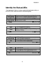
Observe the LEDs as the router powers up. The LEDs will go
through a flashing pattern as the power-up diagnostics are performed.
After the power-up diagnostics are finished, the Power LED will go
from red to green.
The console will also display testing and initialization messages as it
performs these tasks (if this is the first time the router has been
powered up on this console, the display may be unreadable until the
next step is performed).
Enter at least one [RETURN] (up to three if necessary) in order for the
router to determine the baud rate of the terminal used for the console
(i.e., autobaud). The following information will now be seen on the
console connected to the router :
Terminals supported:
ansi, avt, ibm3101, qvt109, qvt102, qvt119,
tvi925, tvi950, vt52, vt100, wyse-50, wyse-vp,
teletype
Enter terminal type:
Select the terminal type being used if listed and enter its name (in lower
case) at the prompt, or choose the terminal type teletype if your
terminal is not listed. This terminal type operates in scroll mode and
may be used successfully until a custom terminal definition is created.
Login and Enter the Required Configuration
At the login screen type a 1 and the default password to enter the menu
system of the router. The default password is BRIDGE (case
sensitive) and should be changed if security is desired.
With the options of the built-in menu system, the router may be
configured to operate within your environment.
Refer to the router PPP Menus Reference Manual file on the
accompanying CD-ROM for a complete description of all the Menu
Options.