


19
CHAPTER 4: Installation
• Plug any local mouse into the local unit’s 6-pin mini-DIN female connector
labeled with the word “Local” and a mouse icon.
Make a last pair of attachments to the connectors on the local unit’s rear panel:
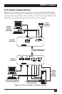
• Attach the SC male connectors at the local-unit end of your duplex fiber
cabling to the local unit’s SC female connectors. (The extender’s SC
connectors are keyed so that you can’t plug the fiber cable in the wrong way.)
Make sure that this fiber cabling, from here all the way to the remote unit, is
either 62.5/125-µm or 50/125-µm multimode type for the Extender II
(ACS250A-R2) or is 9/125-µm single-mode type for the Extender II-SM
(ACS251A-R2). It can either be a single cable that will run all the way to the
remote unit or a patch cable that will run to your fiber-distribution closet. Just
keep in mind that the more fiber connectors the extender’s optical signal runs
through, the more it attenuates.
• Plug the output cord of one of the extender’s included power supplies into the
2.1-mm barrel jack on the local unit’s rear panel. (The two power supplies are
identical, so you can use either one.) Attach the female end of the power
supply’s input cord to the IEC 320 male inlet on the transformer. Plug the
other end of the input cord into a working AC outlet. The local unit should
power up immediately—it has no ON/OFF switch. The green Status LED on
its front panel should begin flashing to show that it isn’t getting a video signal
from the CPU yet.
Don’t power up the attached devices yet—wait until you’re ready to test the
system after installing the remote unit and remote equipment.
CAUTION!
Do not attach anything to the 8-pin mini-DIN connector labeled
“Service” on the local unit’s rear panel, which is reserved for
manufacturer use. Doing so could severely damage the extender and
any attached equipment!