


31
CHAPTER 3: Configuration
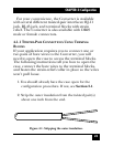
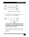
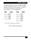
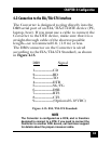
Signal Pin# Pin# Signal
XMT+ 3---------------3XMT+
XMT- 4---------------4XMT-
Figure 4-12. RJ-11 Cable (2-wire).
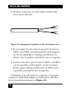
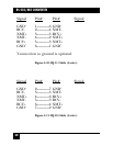
Signal Pin# Pin# Signal
XMT+ 4--------------4 XMT+
XMT- 5--------------5 XMT-
Figure 4-13. RJ-45 Cable (2-wire).
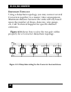
4.2 Wiring for Multipoint Circuits
The Converter supports multipoint applications
using a daisychain topology. This topology requires
special wiring, as well as specific DIP-switch settings
for master and slave units. Refer to Table 3-3 for
multipoint DIP switch settings.