


15
CHAPTER 3: Configuration
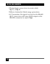
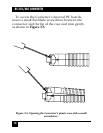
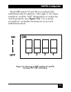
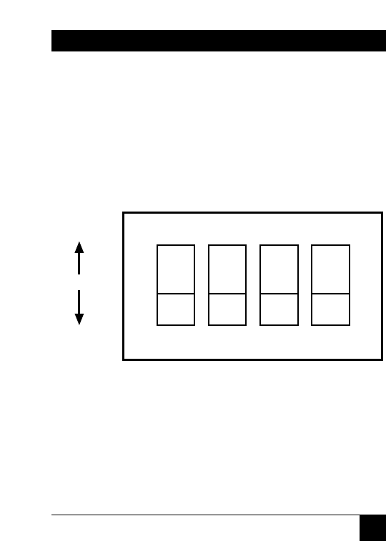
Both DIP switch S1 and S2 are marked with
individual switch numbers 1 through 4. Use these
numbers, and the “ON” designation to orient the
switch properly (see Figure 3-4). Use a small
screwdriver or similar instrument to set each
individual switch.
1 2 3 4
ON
ON
OFF
Figure 3-4. Close-up of DIP switches S1 and S2,
showing ON/OFF orientation.