724-746-5500 | blackbox.com
Page 8
724-746-5500 | blackbox.com
ServSensor EXP DC16
2.3 Hardware Description
2.3.1 Front Panel
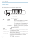
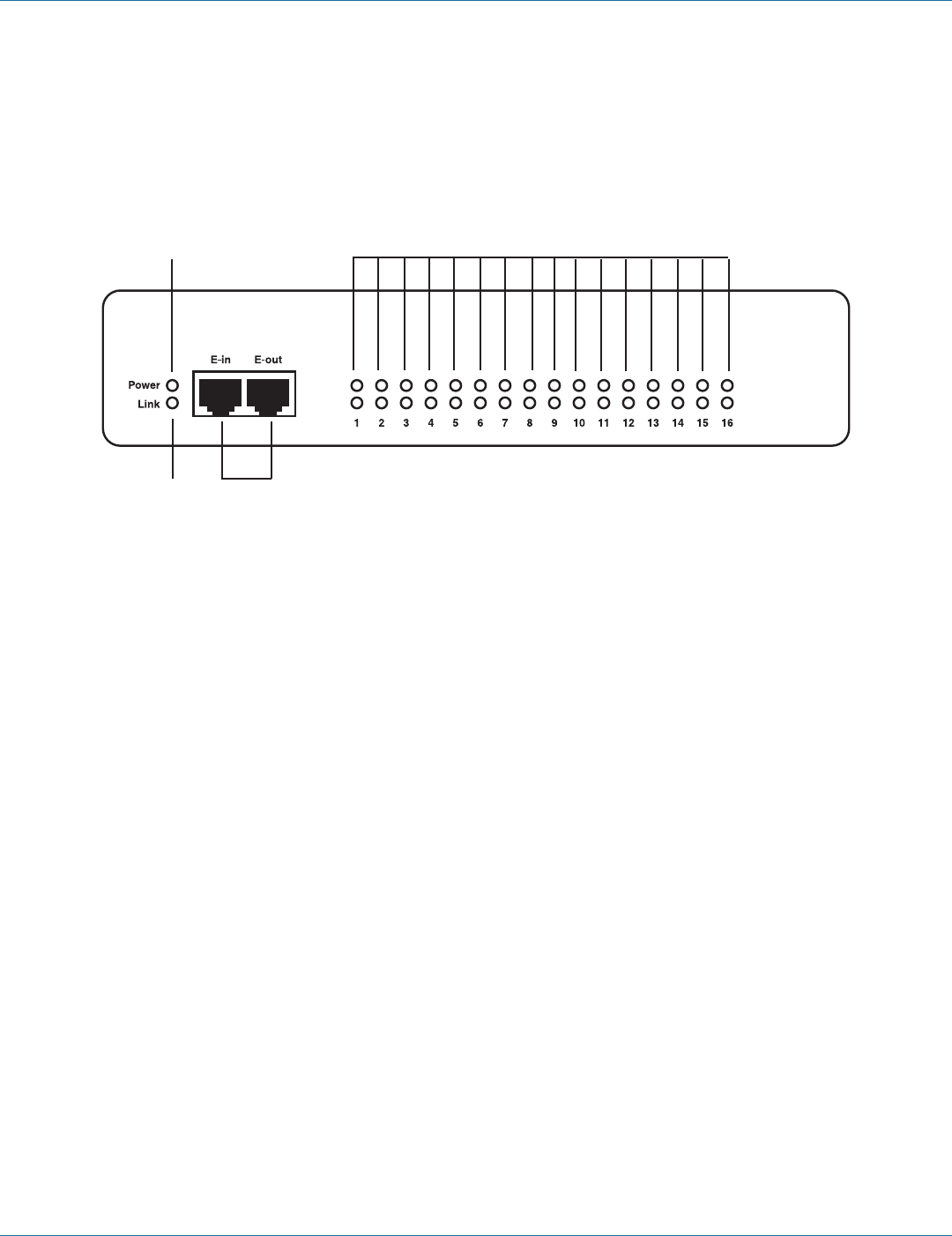
Figure 2-1 shows the ServSensor EXP DC16’s front panel, and Table 2-1 describes its components.
1
2
3
4
Figure 2-1. Front panel.
Table 2-1. Front panel components.
Number Component Description
1 Power LED Lights continuously when the ServSensor EXP DC16 is powered on.
If the LED is flashing, there is a problem with the CPU.
2 Link LED Lights when a network connection is present.
3 RJ-45 ports Expansion In/Expansion Out ports. These ports are named E-in and
E-out. The E-in port connects to your ServSensor V4E base unit via a
CAT5e straight-through cable. The E-out port is used to daisychain
additional expansion modules via a CAT5e straight-through cable.
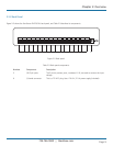
4 Status/Online LEDs 1–16 LEDs numbered 1–16 indicate the connectivity status of the sensors
connected to each port. These LEDs also indicate system status
during various operations.
Table 2-2. Status/Online LED functions.
Function Description
Upgrade in progress The red LEDs will move from left to right to indicate activity, and the green LEDs indicate
overall progress of the upgrade. When all the red lights are off and all the green lights are
on, the upgrade/recovery process is complete.
Unit is operating in safe mode Used when the ServSensor EXP DC16 loads the operating system (OS) with a minimal set
of drivers. If your device enters safe mode after rebooting, contact Black Box Technical
Support at 724-746-5500 or info@blackbox.com.
Unit is in recovery mode The ServSensor EXP DC16 may enter recovery mode if a firmware upgrade is incomplete.
The unit displays a continuously lit row of red LEDs during recovery mode. If your device
enters recovery mode, contact Black Box Technical Support at 724-746-5500 or
info@blackbox.com.


