


12
RS-232↔485/422 CONVERTERS
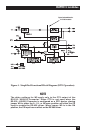
Driver Enabled by Data
The RS-485 driver can also be enabled without requiring an RS-232 control lead to
be asserted. When jumper W15 is placed in the B-C position, the driver is enabled
when data is received on the RS-232 port of the RS-232↔485/422 Converter. As
soon as the first bit of the first character is received at the RS-232 port, the RS-485
driver is enabled and an internal timer is started. The timer begins its “time out”
on a low (0) to high (1) transition of data. When the timer times out, the RS-485
driver is disabled. Jumper W17 allows this timeout delay to be set for 0.15, 0.7, 2, 7,
or 70 msec.
NOTE
There is a limitation to using this “DATA ENABLES DRIVER” feature. At
data rates above 64 Kbps, the first character in the data stream will be
garbled by the Converter. If higher data rates are required, transmit a
<break> if possible, or a <nul> character before each message. This will
enable the RS-485 driver, activate the timer, and allow the message to
be transmitted without errors. The receiving device will need to ignore
the first character received.
Driver Constantly Enabled (4 Wire Only)
The RS-485 driver can be constantly enabled by setting jumper W9 to the ON
position.
3.1.6 H
ALF
-D
UPLEX
T
URNAROUND
D
ELAY
When operating in half-duplex mode (jumper W8 in the HALF position [B-C
position]), the RS-232↔485/422 Converter adds a small delay each time it stops
transmitting data and prepares to receive data. This delay allows the RS-485
interface and transmission line time to stabilize, thus reducing the possibility of
garbled data being received at the end of a message.
The turnaround delays are 0 (W16 in position A), 0.1 msec (W16 in position B),
1 msec (W16 in position C), 5 msec (W16 in position D), and 35 msec (W16 in
position E).
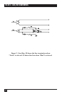
3.1.7 RS-485 I
NTERFACE
T
ERMINATED OR
U
NTERMINATED
Some distortion on the twisted-pair line may be caused by impedance mismatch
from the different devices connected to the line. To help eliminate this type of
distortion, the RS-485 interface can be terminated with a resistor network at the
receiver input pins (RXA and RXB) via switch S2. When S2 is placed in the
“TERM” position, the resistor network is connected across the line. When S2 is
placed in the “UNTERM” position, no connection to the resistor network is made
and the line is not terminated.