


27
CHAPTER 3: Installation
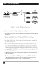
7. Since all the remote PLC stations must be inactive until addressed, the RS-485
driver of each remote RS-232↔485/422 Converter must not be constantly
enabled (W9 of each remote RS-232↔485/422 Converter must be set to a
position other than ON). The remote PLCs are fairly far from the industrial
controller in our example, so it would be wise to set the CTS Delay (jumper
W9) for 10 msec. This allows the line to stabilize after a remote PLC becomes
active but before it starts to transmit.
8. Set jumper W9 on the RS-232↔485/422 Converter connected to the
industrial controller to the ON position. This allows the industrial controller
to transmit to the remote PLCs without having to wait for any delay period.
9. Set jumper W15 of each remote RS-232↔485/422 Converter and the master
RS-232↔485/422 Converter to the A-B position. This allows the
RS-485 driver to be enabled via the RS-232 control lead.
10. Jumpers W16 and W17 are not used in this application and may be set in any
position without affecting the operation of the unit.
11. This completes the configuration procedure. The system can now be
activated.