


9
IEEE 1284 SERIAL TO PARALLEL CONVERTER
3. Configuration
3.1 Configuration Switches
The Converter uses a set of eight external DIP switches that allow configuration to
a wide range of applications. Because all eight switches are in one externally
accessible DIP-switch package, there is no need to open the case for configuration.
The configuration switches allow you to select data rates, parity, word length, and
flow-control selection.
To set the switches:
1. Open the Converter’s case by inserting a small flat-blade screwdriver in the
slot on either side of the case and twisting gently.
2. Having exposed the PC board, you will see the miniature DIP-switch packet on
the side of the board nearest the Centronics
®
connector.
3. Use a small screwdriver and gently push each switch to its proper setting. The
ON position is printed on the switch packet.
4. Fit the case halves and end plate together and push to snap closed.
3.2 Detailed Switch Settings
The DIP switches on the Converter’s PC board are labeled 1 through 8. Only
switches 1 through 4 are used. Switches 5 through 8 have no function.
S
WITCH
1: H
ARDWARE
/S
OFTWARE
C
ONTROL
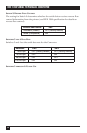
The setting for Switch 1 determines whether the Converter will use hardware or
software (X-on/X-off) flow control.
Flow Control SW1
Hardware OFF (factory default)
Software ON