


12
IEEE 1284 SERIAL TO PARALLEL CONVERTER
5. Operation
Once the Converter is properly configured and installed, it should operate
transparently—as if it were a standard cable connection. There is no ON/OFF
switch.
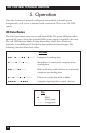
LED Status Monitors
The Converter features two easy-to-read status LEDs. The green LED glows when
optional AC power (from the optional PS095 power supply) is applied to the unit.
The red LED indicator blinks to show data activity. Since there is only one
indicator, it uses different LED codes to demonstrate various messages. The
following chart describes these codes.
LED Codes
●●— ● ——— ●●— ● ——— Computer is sending data.
● ——— ● ——— ● ——— Serial device is connected; computer is not
sending data.
●●——— ●●——— Both serial and parallel devices are connected;
computer not sending data.
● — ● ——— ● — ● ———— Printer not ready, data held in buffer.
●●●●———●●●● Computer ignoring flow control, data lost.
Key
● Blink
— Short pause
——— Long pause