


724-746-5500 | blackbox.com
724-746-5500 | blackbox.com
Page 13
Chapter 3: Assembly and Installation
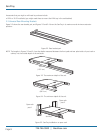
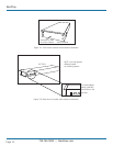
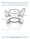
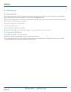
7. Slide out the console drawer. Push the KVM module evenly toward the drawer and secure both units using the attached
thumbscrews. See Figure 3-10.
Thumbscrews (permanently
attached to the tray)
Console drawer
KVM module
Figure 3-10. Securing the KVM module to the console drawer.
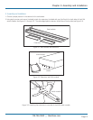
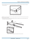
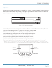
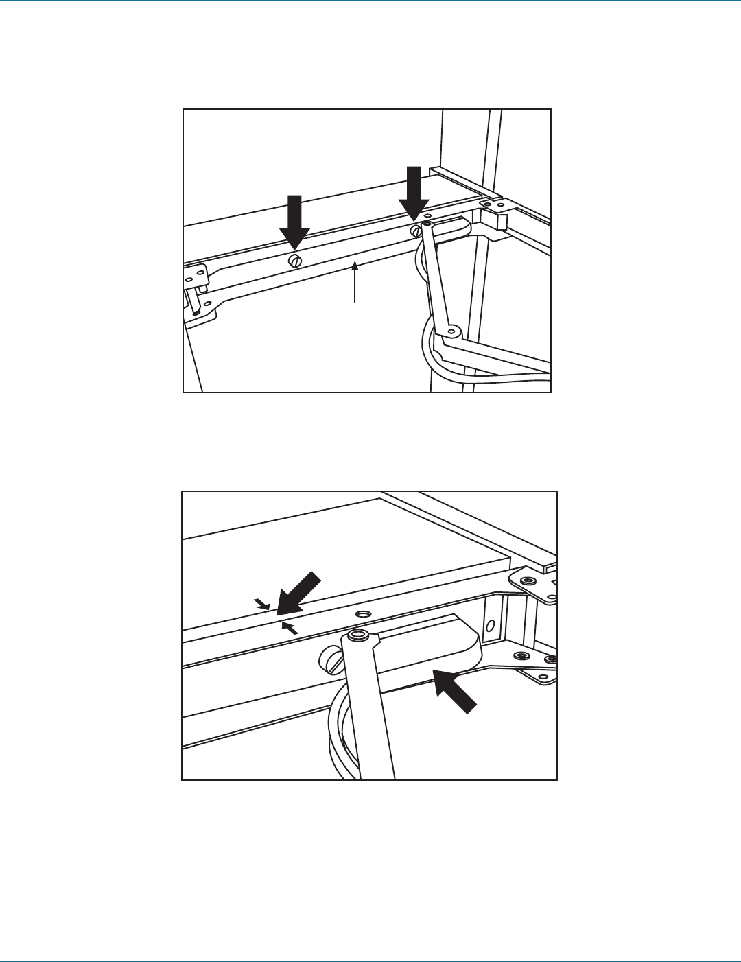
8. Make sure the Centronics connectors on the KVM module and attached cable are firmly mated. See Figure 3-11.
Centronics
connector
on cable
5
⁄16" (8 mm)
Figure 3-11. Centronics connectors.
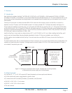
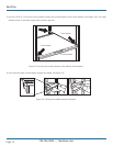
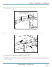
9. Connect the power supply to the barrel connector on the KVM module.
10. For operation, pull out the drawer from the 4-post rack or cabinet and latch it in the extended position. A locking mechanism
locks the drawer when it’s pulled out, pushed in, or folded down. When not in use, push in the drawer, then fold down, lock,
and secure the display.