


724-746-5500 | blackbox.com
724-746-5500 | blackbox.com
Page 15
Chapter 4: Operation
4. Operation
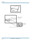
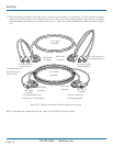
Once the ServTray is installed and connected to a PS/2 or USB CPU or ServSwitch, it’s ready for operation. Control the unit via the
buttons on the LCD panel (labeled 1 and 2 in Figure 4-1) and the LCD panel power switch (labeled 3 in Figure 4-1). Monitor the
status via the keyboard status indicators (labeled 4, 5, and 6 in Figure 4-1).
1
6
5
4
3
2
1
2
Figure 4-1. The ServTray’s components.
1. Use the LCD panel menu buttons (1 in Figure 4-1) to activate the OSD menu to set the LCD panel as an ordinary LCD montior.
2. Use the LCD panel adjustment buttons (2 in Figure 4-1) to adjust settings for the LCD panel.
3. Switch the power to the LCD panel on or off via the power switch (3 in Figure 4-1).
4. Use the keyboard status indicators (Num Lock, Caps Lock, and Scroll Lock) to view status.
• The Num Lock Key LED (labeled 4) shows the Keyboard Num Lock Status (on or off).
• The Caps Lock Key LED (labeled 5) shows the Keyboard Caps Lock Status (on or off).
• The Scroll Lock Key LED (labeled 6) shows the Keyboard Scroll Lock Status (on or off).
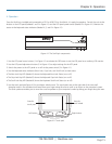
5. Use the touch pad (see Figure 4-2) to simulate a wheel mouse. The touch pad’s area to the right side of the two small
triangular marks is the simulated scroll area. Move your finger along this area to scroll up or down on the computer’s screen.
The touch pad area enables you to move the cursor anywhere on your computer’s screen by sliding your finger along this area.
Area for
touch pad
Left button
Area for
scroll wheel
Right button
Figure 4-2. Touch pad.