


724-746-5500 | blackbox.com
Page 10
VDSL2 Line Power Ethernet Extender Kit
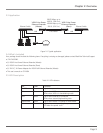
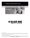
2.6 Front and Back Panels
Figures 2-2 and 2-3 show the master unit’s front and back panels and describe their components.
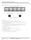
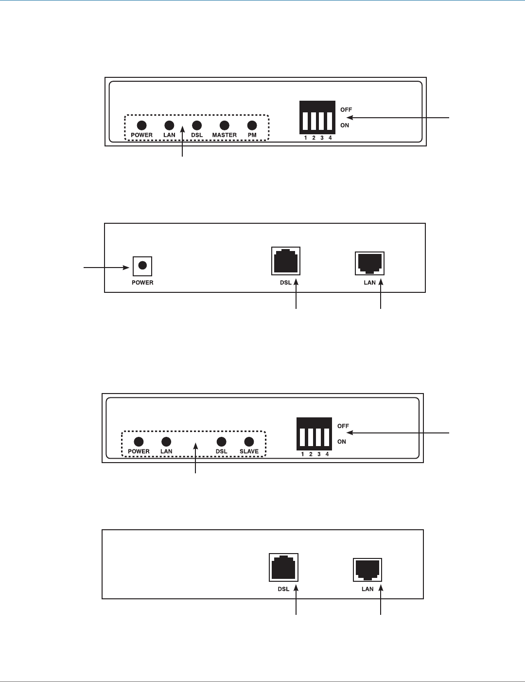
Figure 2-4. Slave front panel.
Figure 2-5. Slave rear panel.
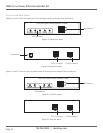
Power Input
RJ-11 Connector RJ-45 Connector
LED Indicators
DIP Switches
RJ-11 Connector RJ-45 Connector
LED Indicators
DIP Switches
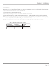
Figures 2-4 and 2-5 show the front and back panels of the slave unit and describe their components.
Figure 2-2. Master front panel.
Figure 2-3. Master rear panel.
VDSL Line Power Ethernet Extender—Slave
VDSL Line Power Ethernet Extender—Master