


Servicing Information
81
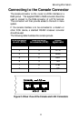
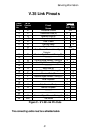
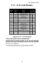
V.35 Link Pinouts
DB25
Contact
No.
M.34
Contact
No.
Circuit
Name
Direction
To From
DCE DCE
1 A
Protective Ground
NA
2 P
Transmitted Data (A)
X
3 R
Received Data (A)
X
4 C
Request to Send
X
5 D
Clear to send
X
6 E
Data Set Ready
X
7 B
Signal Ground
NA
8 F
Data Channel Received Line Signal
Detector
X
9 X
Receiver Signal Element Timing (B)
X
10
----------
11 W
Terminal Signal Element Timing (B)
X
12 AA
Send Signal Element Timing (B)
X
13 ----------
14 S
Send Data (B)
X
15 Y
Send Signal Element Timing (A)
X
16 T
Received Data (B)
X
17 V
Received Signal Element Timing (A)
X
18 L
Local Loopback
X
19
----------
20 H
Data Terminal Ready
X
21 N
Remote Loopback
22
----------
23
----------
24 U
Terminal Signal Element Timing (A)
X
25 NN
Test Mode
X
Figure C - 6 V.35 Link Pin Outs
The connecting cable must be a shielded cable.