


Servicing Information
83
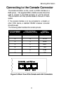
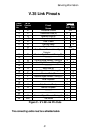
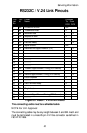
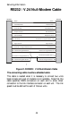
RS232C / V.24 Link Pinouts
Con
tact
No.
Circ
uit
Circuit
Name
Direction
To From
DCE DCE
1 AA Protective Ground NA
2 BA Transmitted Data X
3 BB Received Data X
4 CA Request to Send X
5 ----------
6 CC Data Set Ready X
7 AB Signal Ground NA
8 CF Received Line Signal Detector (CD) X
9 ----------
10 ----------
11 ----------
12 ----------
13 ----------
14 ----------
15 DB Transmit Signal Element Timing (DCE Source) X
16 ----------
17 DD Receive Signal Element Timing (DCE Source) X
18 Local Loopback X
19 ----------
20 CD Data Terminal Ready X
21 ----------
22 CE Ring Indicator X
23 ----------
24 DA Transmit Signal Element Timing (DTE Source) X
25 ----------
Figure C-7 RS232 / V.24 Link Pinouts
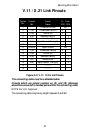
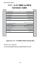
The connecting cable must be a shielded cable.
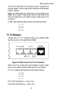
NOTE For U.K. Approval:
The connecting cable may be any length between 0 and 5M. Each end
must be terminated in a male 25 pin X.21 bis connector as defined in
ISO-2110 1989.