


13
CHAPTER 2: Introduction
2.2.5 V.54 D
IAGNOSTICS
V.54 loops are activated manually with the front-panel buttons, or through the
DTE interface. The buttons and the DTE interface can be enabled or disabled
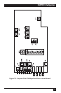
separately by jumpers J7 and J8 (shown in Figure 3-1 and described in Table 3-1).
When you use the line driver as a tail-end to a digital network, the V.54 DLY
jumper in the modems located close to the network should be set to ON to prevent
multiple loopbacks. The delay switch is used to prevent the last modem from
receiving the complete V.54 data sequence and, in turn, being induced into a loop.
2.2.6 T
EST
-P
ATTERN
G
ENERATOR AND
R
ECEIVER
This feature allows for easy and quick testing of the local modem as well as the
communication link. When the PATT button on the front panel is pressed, the
circuit sends and checks a standard 511-bit pseudo-random pattern. If the modem
encounters errors, the ERR LED remains ON or blinks.
The test can be carried out in local analog loopback, in remote digital loopback, or
in normal point-to-point operation opposite a remote line driver modem. Press the
PATT pushbutton on the remote unit or connect a Bit Error Rate Tester that uses
the standard 511-bit pattern.
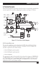
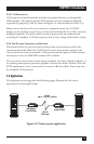
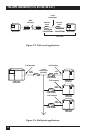
2.3 Applications
The diagrams on this page and the following pages illustrate the line driver
operating in various applications.
Figure 2-2. Point-to-point application.
AS/400
®
256-kbps
Line Driver
256-kbps
Line Driver
AS/400
19.2 to
256 kbps
4-wire
Up to 11.8 mi. (19 km)