


34
256-KBPS LINE DRIVER (V.35, RS-530, OR X.21)
fuse rated for the required amount of current. You must avoid using repaired fuses
or short-circuiting the fuse holders. The fuse, and one replacement fuse, are
located in the top part of the mains connector on the line driver’s rear panel. The
nominal current value of the fuse is 0.125 A for 230-VAC operation or 0.25 A for
115-VAC operation.
Whenever it is likely that the protection offered by the fuse has been impaired, the
unit must be made inoperative and secured against any unintended operation.
After you have attached the power cord and have made sure that the cord is
properly grounded, you can plug the power cord into a working mains outlet.
CAUTION!
The unit has no power switch. It starts operating as soon as power
of the proper type is applied to its POWER connector.
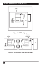
4.3.2 LINE C
ONNECTION
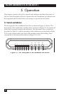
The LINE connection provides an interface for the TX and RX signals between
pairs of line drivers. To make this connection, attach the line wires to the terminal
block on the line driver this way:
• XMT + (remote line driver) to RCV + (local unit);
• XMT – (remote unit) to RCV – (local unit);
• RCV + (remote unit) to XMT + (local unit);
• RCV – (remote unit) to XMT – (local unit);
• Optional: Shield or drain wire (line cable) to ground (local line driver—the
rightmost terminal).
All connections are made on the back of the line driver.
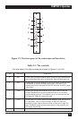
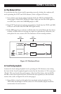
4.3.3 DTE C
ONNECTION
The interface (DTE) connector provides an interface for input/output data, as
well as clock and control signals, between the line driver and a V.35 DTE or DCE.
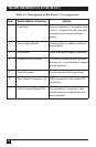
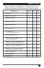
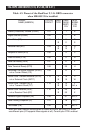
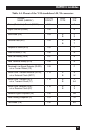
This connector is a standard 34-pin M-block (“M/34”) female. The pinout of this
connector is shown in Table 4-4.