


13
SHM-B ASYNC
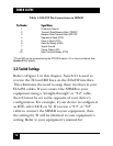
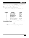
information concerning its DTE/DCE setting. Table 2
gives the EIA-232 pinning of the SHM-B with the
DTE/DCE switch in the DCE position.
Table 2. Pinning with DTE/DCE switch in the DCE position.
PIN NUMBER SIGNAL NAME DIRECTION
1 Protective Ground —————
2 Transmitted Data TD* To DCE
3 Received Data RD* From DCE
4 Request to Send (RTS) To DCE
5 Clear to Send (CTS) From DCE
6 Data Set Ready (DSR) From DCE
7 Signal Ground —————
8 Received Line Signal Detector From DCE
20 Data Terminal Ready (DTR) To DCE
*Pins 2 and 3 (TD and RD) can be reversed using the DTE/DCE switch, S1 on the circuit
board. See Section 3.3 for details.
NOTE
Configure each SHM-B independently. Your local and
remote modems won’t necessarily be configured the same.