


13
SHORT HAUL MODEM (SHM-FSK)
3. Installation
The SHM-FSK units are shipped ready for either full-duplex or half-duplex
multi-drop operation. The jumpers have been factory-set in full-duplex mode.
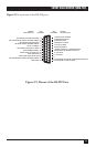
The Master and Remote units are both factory-configured as DCEs (Data
Communications Equipment) with the jumpers on headers P1 and P2 in the
B-C position. Data into the DB25 is on pin 2 and data out is on pin 3. (Also
see Chapter 5, Jumper Settings.)
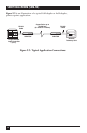
Before installing the SHM-FSK units, make sure that the digital devices to
be connected to the SHM-FSK units are capable of communicating with each
other if connected with a conventional three-wire RS-232 data cable. Once
this has been established, the devices can be connected to the SHM-FSK units
and RS-232 data communications will take place transparently.
NOTE
Make sure that the wire pair to be used for data communications between
SHM-FSK units is connected only to those units; has no branches; has
no attached inductance, capacitance, or resistance; and has no loading
coils, filters or any other load; and that all connections are clean and
solid. Since the data line is transformer-isolated from the rest of the
circuit, neither leg of the data-carrying twisted pair should be grounded.
The installation procedure is as follows:
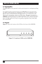
1. Remove the unit’s cover by taking out the four screws on top of the
modem.
2. Set the Remote units for either full- or half-duplex operation by
positioning the jumper on header P4, located behind the DB25
connector. For full-duplex operation, the jumper should be in the B-C
position; for half-duplex, multi-drop operation using RTS line carrier
control, the jumper should be in the A-B position.