


16
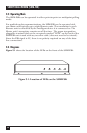
SHORT HAUL MODEM (SHM-FSK)
5. Jumper Settings
There are several configuration options that can be selected by jumpers as
described below. The jumper pins are internal and are identified by lettering
on the circuit board. They are accessed by removing the four retaining screws
on the top cover of the enclosure and removing the cover. Be sure that the
unit is disconnected from power before removing the cover.
5.1 DCE and DTE Settings
Both the SHM-FSK Master and Remote units are configured at the factory
as DCE (Data Communication Equipment) for connection to DTE (Data
Terminal Equipment). A PC, PLC, or multiplexor is usually configured as
DTE. If either the Master or Remote must be changed from DCE to DTE,
move the jumpers on blocks “P1” and “P2,” which are located directly behind
the DB25 RS-232 connector on the rear panel.
5.2 Transmitter Output Level
The SHM-FSK allows the selection of either normal or high-power (HP)
transmitter output. The high-power output has six times greater peak-to-peak
transmitted signal and provides correspondingly greater signal-to-noise ratio.
High-power transmitter operation is generally best in applications involving
sliding contacts or in very noisy EMI environments. However, caution is
advised in some cases since high power carrier signals will result in more
crosstalk to adjacent conductors.
The jumper to select normal or high power is located at position TP2. High
power is selected when the jumper is positioned center to left (marked “H”);
normal output is selected with center to right (marked “N”). When using the
HP setting, the receiver gain should be set to low for data-line lengths under
5000 feet. (see Section 5.3). The factory setting is normal (center to right,
“N”).