


MED100A-0908-3/5 p/n 6132r3
Black Box Corporation - 1000 Park Drive - Lawrence, PA 15055-1018
Tech Support and Ordering: 724-746-5500 - Fax: 724-746-0746
To contact us about Black Box products or services: info@blackbox.com
R
S
-485
2
-
W
ir
e
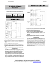
1. Loosen the screws to open the Serial TB Lead Clamps for the G,
H, K, L, and M terminals.
2. Jumper terminal G to terminal K and connect to RS-485 Data A (-)
lead.
3. Jumper terminal H to terminal L and connect to RS-485 Data B (+)
lead.
4. Connect the signal ground lead to terminal M.
5. Tighten the screws to close the Serial TB Lead Clamps. Ensure
the clamps hold the leads securely. However, do not over tighten.
6. Position DIP Switch positions 1 through 5 for t he desired baud
rate.
7. Position DIP Switch positions 7 and 8 to ON for RS-485 2-Wire
mode.
Installation Notes:
Not all RS-485 devices are marked correctly for Data (+) and (-),
so if the slave devices don’t respond after going through the fiber
converter, try swapping the wire pairs polarity to each converter.
When there is no light received from the fiber in, the receive
indicator will be On. You can interconnect or loop back the
transmit fiber on one unit to the receive input on the same unit to
verity the receive light goes out. If the transmit light is lighted all
the time without data, the polarity of the RS-485 is reversed, or
there is not enough bias, or termination loads on the RS-485 bus.
Normal bias before termination is about 3.8 to 4.0 VDC, Data (+)
to (-).
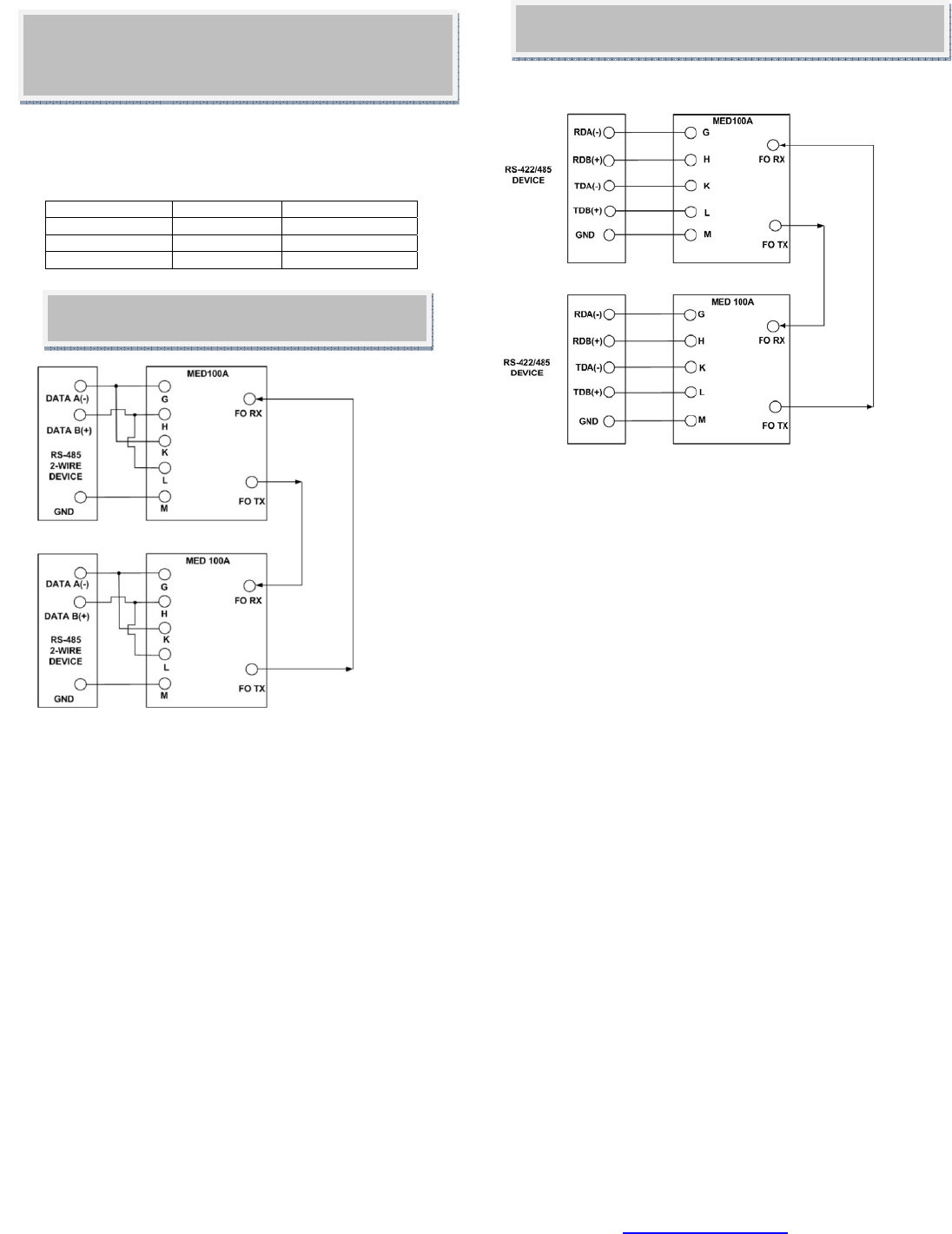
RS-422 / RS-485 4-Wire
1. Loosen the screws to open the Serial TB Lead Clamps for the
G, H, K, L, and M terminals.
2. Connect RS-422/485 signal leads as shown in the diagram.
3. Connect the signal ground lead to terminal M.
4. Tighten the screws to close the Serial TB Lead Clamps.
Ensure the clamps hold the leads securely. However, do not
over tighten.
5. Position DIP Switch positions 1 through 5 for t he desired
baud rate.
6. Position DIP Switch positions 7 to ON and 4 to OFF for RS-
485 4-Wire mode. Set DIP Switch positions 7 and 8 to OFF for
RS-422 mode.
Installation Notes:
Not all RS-485 devices are marked correctly for Data (+) and
(-), so if the slave devices don’t respond after going through
the fiber converter, try swapping the wire pairs polarity to each
converter. When there is no light received from the fiber in, the
receive indicator will be On. You can interconnect or loop back
the transmit fiber on one unit to the receive input on the same
unit to verity the receive light goes out. If the transmit light is
lighted all the time without data, the polarity of the RS-485 is
reversed, or there is not enough bias, or termination loads on
the RS-485 bus. Normal bias before termination is about 3.8
to 4.0 VDC, Data (+) to (-).
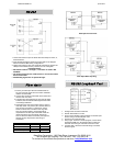
RS-422/RS-485 Mode
Selection
Mode Position 7 Position 8
RS-485 2-Wire ON ON
RS-485 4-Wire ON OFF
RS-422 OFF OFF
1. RS-422/485 mode is selected by positioning DIP Switch
positions 7 and 8 as shown below.