


MED100A-0908-4/5 p/n 6132r3
Black Box Corporation - 1000 Park Drive - Lawrence, PA 15055-1018
Tech Support and Ordering: 724-746-5500 - Fax: 724-746-0746
To contact us about Black Box products or services: info@blackbox.com
RS-232
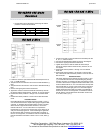
1. Ensure your fiber optic cable is terminated with an
ST type connector. 62.5/125 micro-meter multimode
cable is recommended.
2. Connect the converter’s transmitter to the distant end
receiver and vice-versa.
3. The fiber optic transmitter light is ON in the idle state.
Therefore, the RX indicator will be lighted when data
is not being transferred.
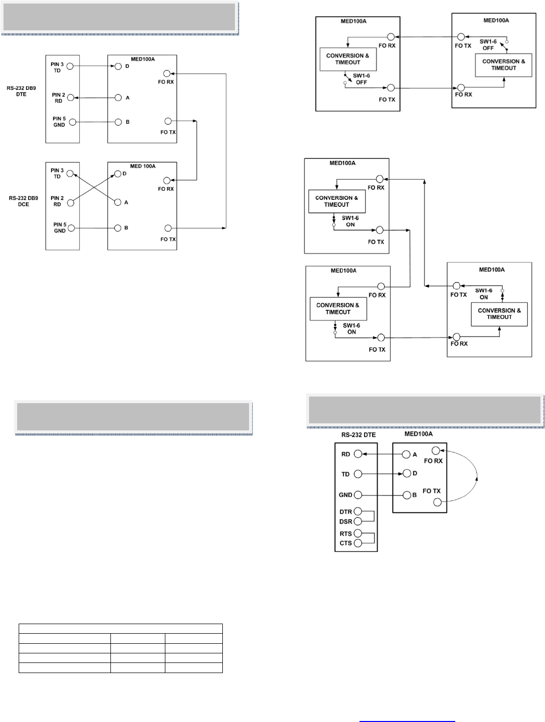
4. DIP Switch SW1-6 is used to select point-to-point or
multi-drop mode. For point-to-point, set the switch to
OFF for both converters. For multi-drop, set the
switch to ON for each converter in the ring. With
SW1-6 in the ON position, receive data will be
looped back to the fiber optic transmitter. Data will
repeat around the ring until it finally reaches its
source. When the data is received by the originator,
timeout circuitry will prevent it from being re-
transmitted.
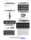
Maximum Converters in a Fiber Ring
Baud Rate RS-232 RS-422/485
19.2 kbps and lower 32 32
38.4 kbps 16 24
115.2 kbps 2 8
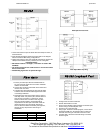
1. Configure the converter for RS-232.
2. Set DIP Switch SW1-6 to OFF.
3. Cross-connect the fiber optic transmitter to the fiber optic
receiver using a multimode patch cord.
4. Connect a PC to the serial port.
5. Using Hyper Terminal or similar program, connect to the
appropriate COM port. Set the baud rate to match the
converter. Ensure Hyper Terminal local echo is OFF.
6. Transmit data. If the same character string is returned,
the test is good.
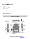
1. Loosen the screws to open the Serial TB Lead Clamps for the D, A,
and B terminals.
2. Insert the RS-232 Signal Leads into the TB. Refer to the diagram
above for DTE and DCE wiring configurations.
3. Tighten the screws to close the Serial TB Lead Clamps. Ensure the
clamps hold the leads securely. However, do not over tighten.
Installation Notes:
• DIP Switch Positions 1 through 5, 7 and 8 are not used in RS-
232 Mode.
• The wiring example shows a DTE device on one end and a DCE
device on the other.
• Handshaking signals are not passed through.
Fiber Optic Point-to-Point
Fiber Optic Multi-drop Ring
Fiber Optic
RS-232 Loopback Test