


6
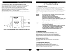
Appendix C. Compression Mode
The Multi DVI System features two video compression modes to enable high resoluiotn
video extension over long distances. Compression modes may be changed with a
simple jumper setting accessible through the front cover. All units must be set to the
same compression mode for proper operation.
The two modes are:
Pixel Compression mode. Suitable for static non motion content. DEFAULT
Jumper J10 IN
Color Compression mode. Suitable for moving content such as DVD movies.
Jumper J10 OUT
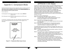
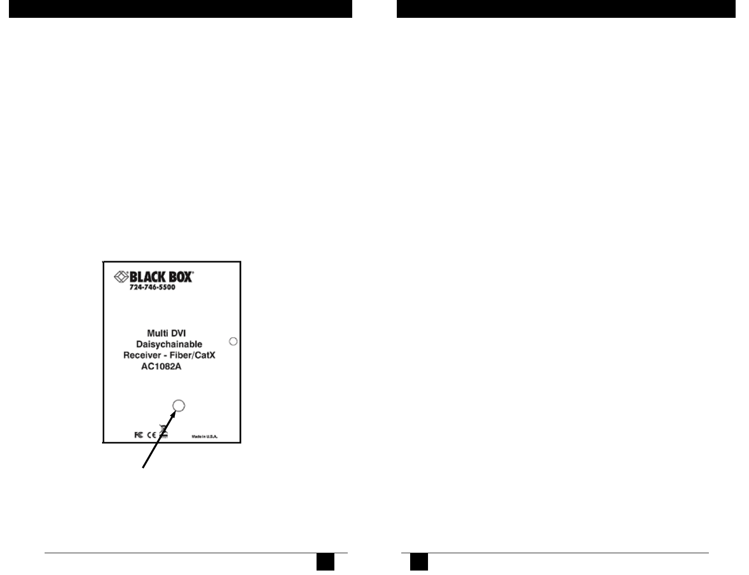
To change the compression mode, remove the compression mode jumper access
cover on the front of the Multi DVI unit and remove or install a jumper on J10
underneath
Figure C-1. Compression Mode Jumper Access
APPENDIX C:Compression Mode
11
MULTI DVI SYSTEM.
11
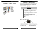
APPENDIX D. DDC Modes
The Multi DVI System features the ability to send DDC display identifiers to the
video source in order to determine display capabilities. The DDC is a data
communication channel used in plug and play devices to accurately report a
displays capabilities and identify the manufacturer. If this data is not available,
the video source may revert to a low resolution or not display at all.
The Multi DVI features the ability to report a Universal Display (MRI Magic
Display) that supports most popular VESA standards in standard or
widescreen formats as well as the ability to clone an actual displays DDC
information that is attached to either the local DVI output of the transmitter or a
receivers DVI output.
The various modes are detailed below:
Mode 1: Universal Display (MRI Magic Display) (DEFAULT)
This mode reports a generic display supporting popular screen
formats and is suitable for most if not all display types.
Mode 2: Clone DDC from DVI Output of transmitter
This mode copies the DDC from a display attached to the local output
of the transmitter.
Mode 3: Clone DDC from receiver (first one if using daisychain options)
This mode copies the DDC data from a display attached to the
receiver (first receiver if a daisychain mode is in use).
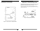
To change modes requires internal jumpers to be changed. See Figure E-1 for
jumper locations (settings are stored in non-volatile RAM and are not lost when
power is removed):
Mode 1: To restore, install jumper J20 while transmitter is power on. No other
cable connections need to made.
Mode 2: To clone DDC from a display connected to the local DVI output of the
transmitter, Install a jumper on J9 and J20 while transmitter is
powered off, then connect the display to the transmitter and power it
on. Remove J20 while transmitter is powered on and leave J9 in. The
video source does not need to be connected.
Mode 3: To clone DDC from a display connected to the DVI output of the
receiver, remove jumper on J9 , ensure J20 is in while transmitter is
powered off, then connect the display to the receiver and the receiver
to the transmitter and power everything on. Remove J20 while
transmitter is powered on and leave J9 off. The video source does
not need to be connected.
12