


Briggs & Stratton Power Products Backup Power System
Owner’s Manual
11
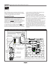
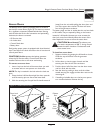
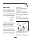
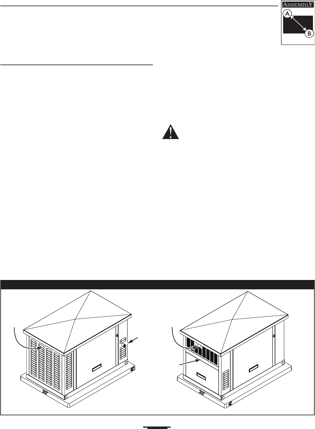
Access Doors
The Backup Power System is equipped with an enclosure
that has four access doors (Figure 4).The doors are named
for a significant component located behind them. Starting
with the side that has the fuel connection and proceeding
clockwise, the doors are named:
• Oil Service door
• Air Intake door
• Control Panel door
• Battery door
Each backup power system is equipped with three identical
keys.These keys fit the locks that secure the oil service and
control panel doors.
CAUTION! Do Not operate the backup generator
unless the Oil Service and/or Control Panel doors are
installed. Failure to do so will cause overheating.
To remove an access door:
1. Insert a key into the lock of the access door you wish
to remove and turn one quarter turn clockwise.
NOTE: The key is retained in the lock when the locks are
open.
2. Grasp the door’s lift handle and pull the door upwards
until the security pins are free of the lower base.
3. With the security pins free, pull the lift handle outward
(away) from the unit while pulling the door down and
out of the upper door channel.The door will come
free of the generator enclosure.
The battery door and the air intake door do not have locks
or lift handles.They are opened by lifting on the louvers
instead of a lift handle. However, you must remove the
door lock screw, found directly above the center of the
door. Replace the screw to secure the access door.
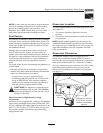
CAUTION!
Burn Hazard! The exhaust port
can reach a temperature of 600° F during use and
remains hot after shutdown. Carelessness could
cause severe burns.
To install an access door:
1. Support the door by grasping the lift handle or louver.
Guide the top of the door into the generator
enclosure.
2. Lift the door up into its upper channel until the
security pins clear the sill of the enclosure.
3. Push the lower half of the door into the door recess
until it is flush with the sides.
4. Seat the door by pushing it down until the rubber
coated security pins engage and the door rests on the
mounting sill.
5. If installing a lockable door, turn the key one quarter
turn counterclockwise. Remove the key.
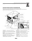
Oil Service Door
Fuel
Inlet
Exhaust
Port
Air Intake Door
Door Lock
Screw
Door
Lock
Screw
Battery Door
Control Panel Door
Figure 4 — Enclosure Access Doors