


Briggs & Stratton Power Products Backup Power System
Owner’s Manual
6
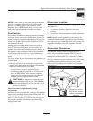
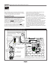
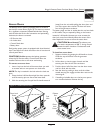
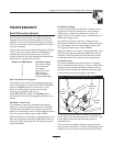
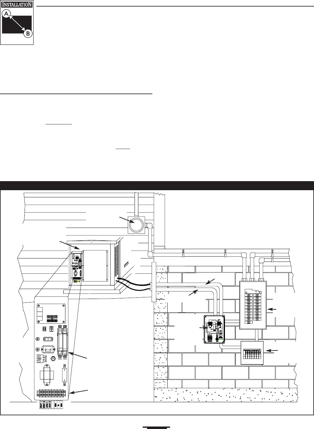
Figure 2 identifies system components and shows typical
installation details.Variations to this illustration are related
to code issues, piping distances and materials.
Essential Circuits
As a Backup Power System owner, it is important that you
clearly identify the circuits in your building that are
"essential" to you. Because the Backup Power System is
equipped with an Automatic Transfer Switch, your selection
of essential circuits will be transferred to the Backup
Power System within 15 seconds (+/- 5 seconds).
It is important that your installer understand which
circuits
you want to include as "Essential Circuits". Depending on
the power consumed by these circuits, most or all of them
can be switched to the Backup Power System for the
duration of normal power interruption.
The essential circuits are gathered in a special circuit
breaker box, referred to as the Essential Circuit “sub-
panel”, that is connected by conduit to the transfer switch.
This breaker box is provided by the installer because it
allows him to use the brand that is most compatible with
your existing electrical service components.
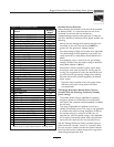
The wattage reference guide shown in Figure 3 will assist
you with your decision-making process. It provides the
wattage used by many ordinary household devices. Use it
as a guide when selecting your essential circuits. Review
this information with your installer and ask about any
technical considerations that might affect the cost of your
installation.
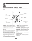
Power Lead
Connections
NEUTRAL to White wire
GND to chassis
Control Signal
Connections
Automatic
Power
Transfer
Switch
Rear of
Control
Panel
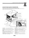
Backup Power
System Generator
Power Leads
Signal Leads
Main
Distribution
Panel
Essential
Circuit
Sub-panel
Utility Power
Meter
Figure 2 — Typical Installation Diagram for Backup Power System