


13
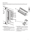
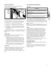
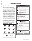
System Control Panel
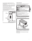
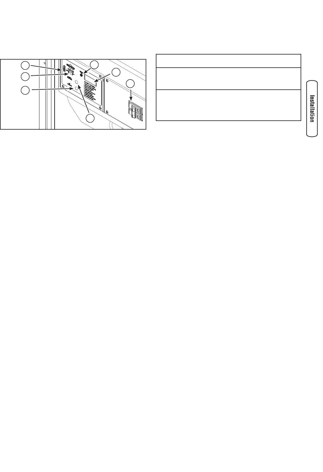
The home generator control panel, located inside the
generator housing, is shown below.
Brief descriptions of the controls used during installation are:
A - Set Exercise Switch — Used to set the exercise cycle.
B - System Switch — Switches modes to OFF and AUTO.
C - 15 Amp Fuse — Protects the DC control circuits.
D - Service Tool — For qualified service personnel ONLY.
E - Digital Display — Displays running time and fault codes.
F - Circuit Breaker — Must be ON to supply power to the
transfer switch.
G - Manual Over-Ride Switch — Turns generator ON or OFF.
More information may be found in Controls in the Operator’s
Manual.
System Switch
This two-position switch is the most important control on
the home generator and is used as follows:
• “AUTO” position is the normal operating position. If
a utility power outage is sensed, the system will start
the generator. When utility power is restored, lets the
engine stabilize internal temperatures, shuts off the
generator, and waits for the next utility power outage.
• “OFF” position turns off running generator, prevents
unit from starting and resets any detected faults.
15 Amp Fuse
Protects the home generator DC control circuits. If the fuse
has ‘blown’ (melted open) or was removed, the engine
cannot crank or start. Replace the fuse using only an
identical ATO 15A fuse. One spare fuse is supplied with the
unit.
Final Installation Considerations
Engine Oil
NOTICE
Any attempt to crank or start the engine before it has been
properly serviced with the recommended oil will result in
equipment failure.
Refer to Maintenance and engine manual for oil fill
information.
Damage to equipment resulting from failure to follow this
instruction will void engine and generator warranty.
•
•
This engine is shipped from the factory pre-run and filled
with synthetic oil (API SJ/CF 5W-30W). This allows for
system operation in the widest range of temperature and
climate conditions. Before starting the engine, check oil level
and ensure that engine is serviced as described in the engine
operator’s manual.
NOTE: The use of synthetic oil does not alter the required oil
change intervals described in the engine operator’s manual.
Battery
The home generator is supplied with a sealed, valve-
regulated, lead-acid rechargeable 12 Volt DC, AGM type,
55 Amp-Hour battery. The battery cables are connected
at the factory. The unit’s 15 Amp fuse, which isolates
the battery and prevents the unit from starting, has been
removed for shipping. The battery will lose some charge
prior to installation of the generator. If battery voltage
is below 12 Volts, charge the battery. See Battery in the
Operator’s Manual Maintenance section for details.
IMPORTANT: If battery voltage is below 5 Volts, it may not
take a charge and you will need a new battery.
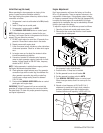
Fuel Supply System
Ensure that all fuel pipe connections are tight, secure and
without leaks.
Ensure that all gas line shutoff valves are OPEN and that
adequate fuel pressure is available whenever automatic
operation is desired.
B
A
C
D
F
G
E