


15
9. Push and hold MANUAL OVER-RIDE button on control
panel again until engine stops.
10. Turn the service disconnect to the transfer switch off.
After a short time delay, the transfer switch will connect
to the generator.
11. Load generator to full load.
12. Connect an accurate frequency meter to the load side of
the generator’s main circuit breaker. Frequency should
be above 57.0 Hz.
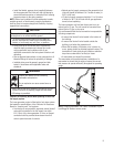
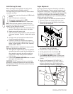
13. If frequency is below 57.0 Hz, slowly rotate the
governor adjustment nut or screw clockwise and/or
counterclockwise until frequency is above 57.0 Hz.
14. Turn the service disconnect to the transfer switch on.
The transfer switch will connect to the utility after five
minutes.
15. After the engine has stopped running,
• If an adjustment was made in step 13, repeat steps
3 through 9.
• If an adjustment was not made in step 13, proceed
to step 16.
IMPORTANT: If the no load frequency falls out of the no
load parameter after full load adjustment is made, contact an
authorized service center.
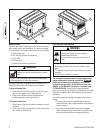
16. Reinstall the circuit breaker cover to the air intake
guard.
17. Close the oil drain and control panel access doors.
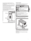
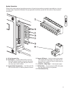
Controls
See the Operator’s Manual for complete description of the
home generator controls.
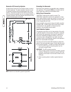
Operation
Automatic Operation Sequence
The generator’s control panel houses a logic control circuit
board. This control board constantly monitors utility power
source voltage. Should that voltage drop below a preset
level, control board action will signal the engine to crank and
start.
When utility source voltage is restored above a preset
voltage level, the engine is signaled to shut down.
The actual system operation is not adjustable and is
sequenced by sensors and timers on the control board, as
follows:
Utility Voltage Dropout Sensor
• This sensor monitors utility source voltage.
• If utility source voltage drops below about 70 percent
of the nominal supply voltage, the sensor energizes a
10 second timer. The timer is used to ‘sense’ brown-
outs.
• Once the timer has expired, the engine will crank and
start.
Utility Voltage Pickup Sensor
This sensor monitors utility power supply voltage. When that
voltage is restored above 80 percent of the nominal source
voltage, a time delay starts timing and the engine will go to
engine cool-down.
Engine Cool-down Timer
• When the load is transferred back to the utility power
source, the engine cool-down timer starts timing.
• The timer will run for about one minute, then the
generator will stop.
• Minimum engine run time is 5 minutes.