


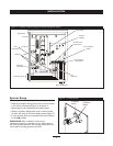
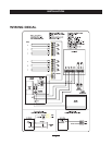

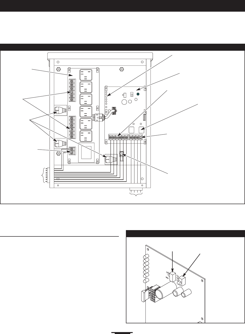
Figure 2 — A Typical Installation Diagram for Power Management System
Ground Lug
To Transfer Switch
Air Conditioner
Relays
Load
Connection
Controle
Module
Generator
Connection
Air Conditioner
Connections
8
INSTALLATION
Wireways
System Setup
You must perform the following before operating the system:
• Place the 2 position sliding switch on the control module
in the NG or LP position (Figure 3), whichever is
appropriate for the installed home standby system.
• Place the 3 position sliding switch on the control module
to match the rating of the home standby system (Figure 3).
• In main breaker panel, turn selected load circuit breakers
to the ON position.
IMPORTANT:After installation of the power
management system is complete, turn on utility power to
the home standby generator and transfer switch.Wait one
minute before turning generator to AUTO.
Figure 3 — Control Module
2 Position
Switch
3 Position
Switch
Relay Board
To Air Conditioners
Transfer Switch
Connections
Green LED’s