


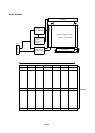
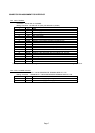
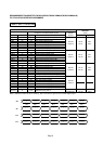

CONNECTOR PIN ASSIGNMENT FOR INTERFACE
CN1 INPUT SIGNAL
Connector : DF19L-20P-1H / HIROSE
Mating Connector : DF19G-20S-1F (FPC), DF19G-20S-1C (Cable)
Terminal No. Symbol Function
1 VSS GND
2 VDD Power Supply : +3.3V
3 VDD Power Supply : +3.3V
4 VEDID DDC 3.3V power
5 NC Non-Connection
6 CLKEDID DDC clock
7 DATAEDIE DDC data
8 RxIN0- Negative LVDS differential data input (R0-R5,G0)
9 RxIN0+ Positive LVDS differential data input (R0-R5,G0)
10 VSS GND
11 RxIN1- Negative LVDS differential data input (G1-G5, B0-B1)
12 RxIN1+ Positive LVDS differential data input (G1-G5, B0-B1)
13 VSS GND
14 RxIN2- Negative LVDS differential data input (B2-B5, HS, VS, DE)
15 RxIN2+ Positive LVDS differential data input (B2-B5, HS, VS, DE)
16 VSS GND
17 CLK- Clock Signal(-)
18 CLK+ Clock Signal(+)
19 VSS GND
20 VSS GND
Note 1) Please connect GND pin to ground. Don't use it as no-connect nor connection with high impedance.
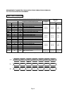
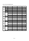
CN2 CCFL POWER SOURCE
Connector : BHSR-02VS-1 / JAPAN SOLDERLESS TERMINAL MFG CO., LTD.
Mating Connector : SM02B-BHS-1 / JAPAN SOLDERLESS TERMINAL MFG CO., LTD.
Terminal No. Symbol Function
1 VFLH CCFL Power Supply ( high voltage)
2 VFLL CCFL Power Supply (low voltage)
Page 7