


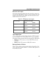

REQUIREMENTS/SPECIFICATIONS
2-11
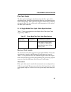
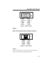
Figure 2-3. TPIM-T1 Pinouts
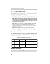
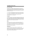
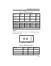
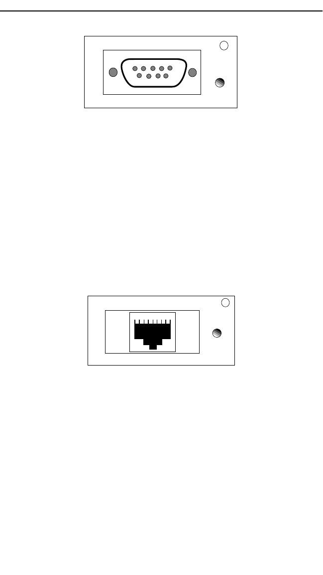
TPIM-T2
TPIM-T2 provides an RJ45 connector that supports UTP cabling.
Figure 2-4 shows pinouts for Ring Out and Ring In applications.
Figure 2-4. TPIM-T2 Pinouts
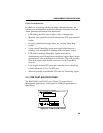
TPIM-T4
TPIM-T4 is an RJ45 connector that supports STP cabling. Figure 2-5
shows pinouts for Ring Out and Ring In applications.
RING OUT
1. Transmit +
2. Ground
3. +5V at 250 mA
4. Ground
5. Receive -
6. Transmit -
7. Ground
8. Ground
9. Receive +
TPIM-T1
LNK
5 4 3 2 1
9 8 7 6
RING IN
1. Receive +
2. Ground
3. +5V at 250 mA
4. Ground
5. Transmit -
6. Receive -
7. Ground
8. Ground
9. Transmit +
RING OUT
1. Not Used
2. Not Used
3. Receive -
4. Transmit +
5. Transmit -
6. Receive +
7. Not Used
8. Not Used
RING IN
1. Not Used
2. Not Used
3. Transmit -
4. Receive +
5. Receive -
6. Transmit +
7. Not Used
8. Not Used
TPIM-T2
LNK
1 2 3 4 5 6 7 8