


Overview
FE Switch Module User Guide Page 1-3
1.2 OVERVIEW
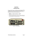
Cabletron Systems Fast Ethernet Switch Modules connect the ATX hub
to a maximum of four individual Ethernet IEEE 802.3 Local Area
Networks (LANs). Through the ATX backplane, connectivity to other
Fast Ethernet devices, as well as connectivity to FDDI, Token Ring, and
Ethernet networks is supported. You can configure the module to support
Transparent Spanning Tree, Source Routing, or Source Routing
Transparent Bridging on each of the FDDI, Token Ring, or Ethernet ports
of the ATX. The ATX is also able to translate higher level protocols to
allow communications between end-nodes on Ethernet and end-nodes on
FDDI or Token Ring; protocols translated include TCP/IP, Novel
NetWare, and AppleTalk Phase II.
The switch modules include processing circuitry for receiving and
forwarding data packets between the connected devices. Each module
contains an offline button as well as several light emitting diodes (LEDs)
that indicate the operational status of the module and the individual ports.
You can install the switch modules in any of the five interface slots of the
ATX. Each switch module provides connectivity to four distinct 100 Mb
LANs.
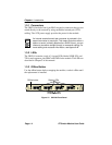
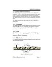
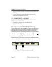
1.3 3H02-04 FE SWITCH MODULE
The 3H02-04 (Figure 1-2) provides connection for four independent
100BASE-TX LANs to the ATX backplane and packet processing engine
(PPE). It includes processing circuitry for receiving and forwarding
packets between the connected 100BASE-TX LANs within each module.
The 3H02-04 contains several LEDs to indicate the module’s operational
status. Each segment has link test enabled and supports receive pair
polarity reversal detection and automatic correction.
The 3H02-04 supports unshielded twisted pair (UTP) and IEEE 802.3
100BASE-TX specification.