


3H08-04 FE Switch Module
FE Switch Module User Guide Page 1-5
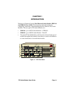
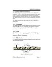
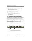
1.4 3H08-04 FE SWITCH MODULE
The 3H08-04 (Figure 1-3) provides connection for four independent
100BASE-FX LANs to the ATX backplane and packet processing engine
(PPE). It includes processing circuitry for receiving and forwarding
packets between the connected 100BASE-FX LANs within each module.
The 3H08-04 contains several LEDs to indicate the module’s operational
status.
The 3H08-04 supports fiber optic and the IEEE 802.3 100BASE-FX
specification.
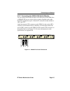
1.4.1 Connectors
The 3H08-04 includes four pairs of fiber optic socket connectors for fiber
optic cabling. Receive (RX) and transmit (TX) connectors are clearly
marked on the front panel of the module. The ATX power supply
provides the power for the module.
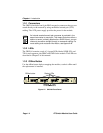
1.4.2 LEDs
The 3H08-04 contains a total of 14 green LEDs labeled LINK, RX, and
TX for each segment, plus PROC and PWR for the module. The LEDs are
described in Chapter 5 of this manual.
1.4.3 Offline Button
Use the offline button before swapping the module, to take it offline until
the replacement is installed.
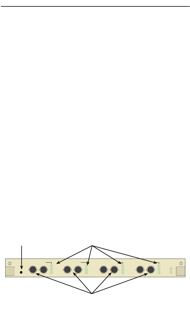
Figure 1-3 3H08-04 Front Panel
OFFLINE
RX
LK
TX
QUAD FAST ETHERNET / 802.3 100BASE-FX
TX RX
SEGMENT 4SEGMENT 3SEGMENT 2 SEGMENT 1
RX
LK
TX
RX
LK
TX
RX
LK
TX
PROC
PWR
TX RX TX RX TX RX
Status LEDs
Offline Button
Fiber Connectors