


1-15
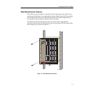
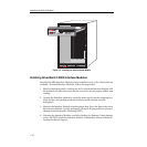
Installing the 9Cx14 Chassis
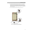
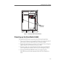
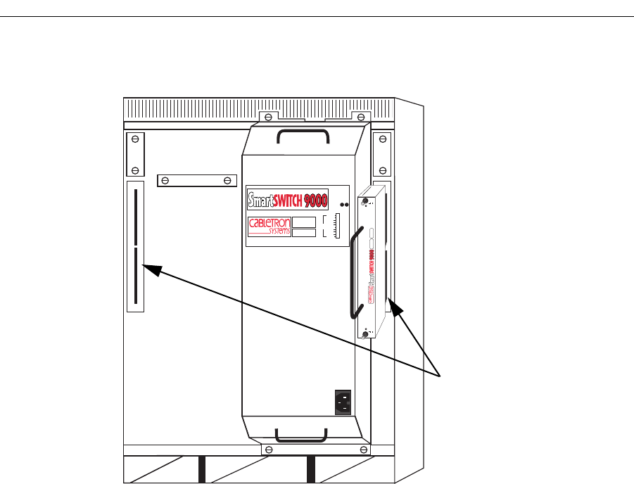
Figure 1-7. Attaching the INB Terminator Modules
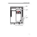
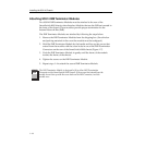
Powering up the SmartSwitch 9000
The SmartSwitch 9000 chassis is powered up by following the steps below:
1. Plug one end of the power cord (supplied with the power supply) into the AC
power socket on the lower right front corner of the power supply.
2. Plug the other end of the power cord into an AC receptacle. Turn on the power
supply using the switch located near the power socket.
3. The power supply uses a soft start feature and does a pre-power diagnostic
check. Outputs become enabled within 5 seconds of turning the power on.
4. Check that the PWR and SMB LEDs on the power supply are green.
If the LEDs are any color other than green, refer to the
Power Supply User’s
Guide
.
100-125v-12A
200-250v-6A
50-60 Hz
POWER SUPPLY MODULE
9C214-1
100%
50%
0%
STATUS
P
W
R
S
N
B
Load
9C614
NON-SECURED
SECURED
NON-SECURED
SECURED
SP
INB
Termination
Connectors