


INSTALLATION
2-7
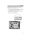
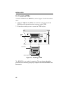
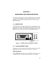
Figure 2-4. TPIM Configuration for Station Applications
NOTE: If the switch locations on a TPIM do not match the example
locations illustrated in Figure 2-4, refer to the TPIM Reference Card
included with the TPIM. The TPIM Reference Card outlines switch
locations and settings. For additional help, call Cabletron Systems
Technical Support Department (see Section 1.5).
Top View
(See Below For Settings)
TPIM-T1/TPIM-T2/TPIM-T4
Phantom Switch Settings
1 = Cabletron Device (Default)
0 = Non-Cabletron Device
RI/RO-STN Switch Settings
RI/RO = Ring In/Ring Out (Default)
S = Station (BRIM-T6 Functional)
P
H
A
N
T
O
M
S RI/RO
1
0
TPIM-F2/TPIM-F3
Fiber Key Settings
Ctron = Cabletron Device
802.5 = BRIM-T6 Functional
RI/RO-STN Switch Settings
RI/RO = Ring In Ring Out (Default)
STN = Station (BRIM-T6 Functional)
S
T
N
RI/RO
8
0
2
.
5
Ctron
PN . . . . .-0X REV
Part
Number