


LANVIEW LEDs
4-2
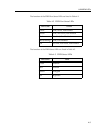
The functions of the System Management Bus (SMB) and CPU LEDs are listed in
Table 4-1.
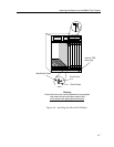
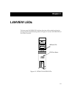
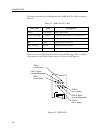
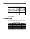
There is one row of FDDI Port Status LEDs for each FDDI ring, FNB-1 and FNB-2.
The functions of the FDDI LEDs are shown in Figure 4-2 and Table 4-2.
Figure 4-2. FDDI LEDs
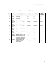
Table 4-1. SMB and CPU LEDs
LED Color
State Description
Green Functional Fully operational.
Yellow (Flashing) Crippled Not fully operational (i.e., one bad port).
Yellow/Green Booting Blinks yellow and green while booting.
Red Reset Normal power-up reset.
Red (Flashing) Failed Fatal error has occurred.
Off Power off Module powered off.
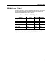
FDDI-1
Port A Status
FDDI-1 Status
(Inserted/Bypassed)
FDDI-1
Port B Status
FDDI-2 Status
(Inserted/Bypassed)
FDDI-2
Port A Status
FDDI-2
Port B Status