


Chapter 3: Testing and Troubleshooting
3-2 FOMIM User’s Guide
5. Disconnect the jumpers from the barrel connector.
6. Using the jumper, attach the optical power meter to one end of one
strand of the link segment.
7. Using the other jumper, attach the other end of the same strand to the
optical source unit.
8. Note the reading on the optical power meter. This is your test level.
9. Subtract the reference level found in Step 4 from the test level to find
your dB loss for the fiber optic link segment, i.e.,
dB loss = Test Level - Reference Level.
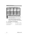
10. Verify that the reading on the receive unit falls within the range
indicated by the Receive Sensitivity and Maximum Receive Input
Power specifications listed in the Fiber Optic Interface section of
Appendix A.
11. Repeat Steps 6 through 10 for the other strand in the link segment.
If the fiber optic link segment does not meet the specifications, it may be
contaminated with dust, dirt, or other contaminants. Try cleaning the
connection at each end of the cable with denatured alcohol, using a soft,
clean, lint free cloth, then repeat the test.
If this does not work, contact Cabletron Systems technical support.
3.1.2 Link Test
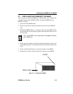
To verify the physical link between your devices, check the LNK LEDs
on your FOMIM and receiving device for the applicable port. If the LEDs
are lit, the proper connection has been made.
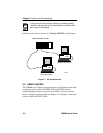
If the LEDs are not lit, perform the following procedure, using a
Cabletron Systems FOT-F3 Fiber Optic Transceiver at the other end of the
cable.
1. Check that power is being supplied to both the FOMIM in the MMAC
chassis and the device at the other end of the link.
2. Reverse the fiber optic cable ends at either the applicable port on the
module or at the device.
3. Check if the LEDs are lit.