


Manager Card
80-10100001-09 3–3
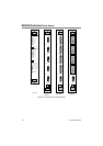
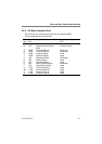
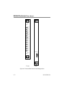
3.2 Front Panel
The front panel of the Manager Card has the following controls and
indicators:
• Transmit and receive data LED’s for the command terminal data
lines. These LED’s display data activity on both the transmit and
receive data circuits.
• AC power indication for each of the power supplies. These
LED’s are fed from the AC power sensing circuits from each
power supply.
• A lock out switch for each of the 13 channels. These are
provided to enable the user to set the poll number for individual
KBU 64 cards. Once the cards have been programmed ALL the
lockout switches must be set to enable the KBU 64s. The
lockout switches can also be used to isolate a KBU card that is
streaming unwanted alarms, so allowing other KBU cards to
have access from the Manager Card.
• An LED for each channel to indicate which channel is actively
selected and in communication with the Manager Card. When
another KBU 64 card is polled that card's LED will light and the
previously selected card LED will extinguish.
3.3 Rear Panel
The command port on Manager Rear Interface Card is a female 25 way
'D' type and uses the same V28 level circuits and pin connections as the
standalone KBU 64.