


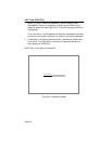
ATTACHING THE CONSOLE
Page 2-4
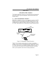
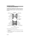
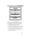
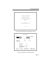
2.2 CONSOLE CABLE CONFIGURATION
A single female DB-9 receptacle provides a Console interface to the
management terminal. Depending on your specific terminal, one of two
cable configurations (9 pin to 25 pin or 9 pin to 9 pin) is used for the
connection to the MRXI Console port. Figure 2-2 shows the pinout for
both cables.
Figure 2-2. Console Cable Pinouts
Connect the console to the MRXI as follows:
1. Attach the male 9-pin connector to the CONSOLE port on the rear
of the MRXI.
2. Attach the female end (25-pin or 9-pin, as applicable) to the COMM
port on the terminal.
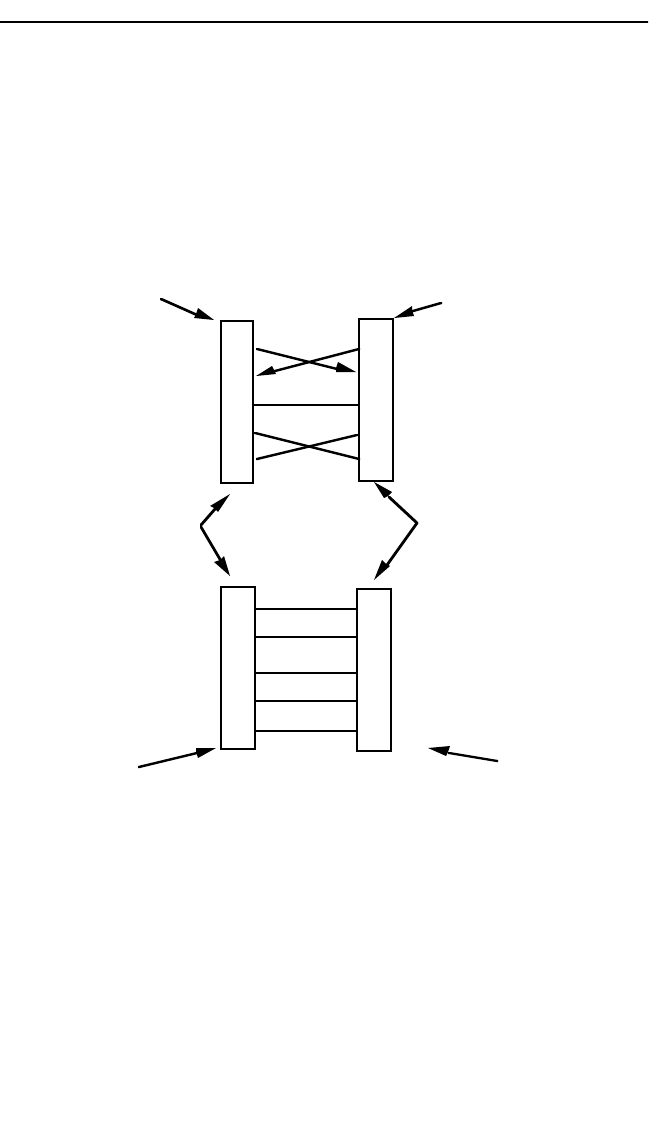
2
3
5
7
8
CONSOLE PORT LOCAL MANAGENT
CONSOLE
TRANSMIT
RECEIVE
RECEIVE
TRANSMIT
REQUEST TO SEND
CLEAR TO SEND
SIGNAL GROUND
REQUEST TO SEND
CLEAR TO SEND
S
IGNAL GROUND
9 PIN TO 9 PIN
CABLE
MALE - DB-9
(9-Pin Connector)
2
3
5
7
8
2
3
5
7
TRANSMIT
RECEIVE
RECEIVE
TRANSMIT
REQUEST TO SEND
CLEAR TO SEND
SIGNAL GROUND
SIGNAL GROUND
9 PIN TO 25 PIN
CABLE
FEMALE - 25 Pin
"D" Shell Connector
20 DATA TERMINAL READY
MALE - DB-9
(9-Pin Connector)
FEMALE - DB-9
(9-Pin Connector)
2
3
5
7
8
C
LEAR TO SEND