


Appendix C: Network Planning and Configuration
Page C-4 NBR-SERIES Installation Guide
- Network propagation delay is the amount of time it takes a packet
to travel from the sending device to the receiving device. Total
propagation delay allowed for the entire network must not exceed
25.6 µs in one direction (51.2 µs round trip). If the total
propagation delay between any two nodes on the network exceeds
25.6 µs, you must use bridges.
• Length - The maximum possible multimode fiber optic cable length is
2
km (2187.2 yards). However, IEEE 802.3 FOIRL specifications
specify a maximum of 1 km (1093.6 yards).
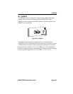
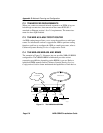
C.1.3 Single Mode Fiber Optic Network
When connecting a single mode fiber optic link segment to an EPIM-F3,
ensure the network meets the following requirements:
• Cable Type - Fiber optic link segments should consist of
8/125 to 12/125 µm single mode fiber optic cabling. You can also use
62.5/125 µm multimode cable with the EPIM-F3; however, multimode
cable allows for greater optical loss, and limits the possible distance to
2 km.
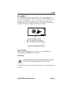
• Attenuation - You must test the fiber optic cable with a fiber optic
attenuation test set adjusted for a 1300 nm wavelength. This test
verifies that the signal loss in a cable falls within the acceptable level
of 10.0 dB or less for any given single mode fiber optic link.
• Budget and Propagation Delay - When you determine the maximum
fiber optic cable length to incorporate fiber runs into your network, you
must calculate and consider the fiber optic budget (a total loss of
10.0 dB or less is permissible between stations) and total network
propagation delay.
- To determine the fiber optic budget, combine the optical loss due
to the fiber optic cable, in-line splices, and fiber optic connectors.
Typical loss for a splice and connector (together) equals 1 dB or
less.