


Ethernet Workgroup Design 6-21
Ethernet
Design Example
As an example, we can examine a network design that is being planned for a
group of Computer-Aided Design (CAD) engineers in a large architectural firm.
These CAD designers want to replace their existing shared Ethernet LAN with a
network that provides greater throughput between their end stations. The
Network Designer, who is already familiar with Ethernet networking, does not
wish to change the technology that the group uses, and has decided that a simple
and cost-effective way to provide more bandwidth to each end station is through
per-port switched Ethernet connections.
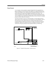
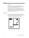
The CAD department consists of 16 CAD designers, 2 CAD image file servers,
and 3 plotters, all in a single facility. The stations have existing 10BASE-T links to
the wiring closet. The CAD department is currently linked to the rest of the
company through an Ethernet connection to a bridge in the Materials Research
department. The Network Designer, hoping to simplify the network, wants to
connect the CAD group directly to the corporate backbone, an FDDI ring.
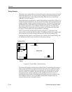
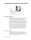
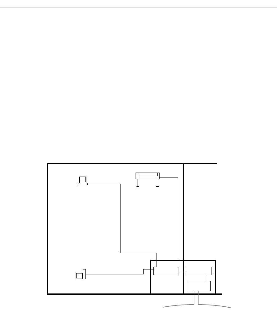
Figure 6-7. High-End Department - Initial Scenario
Plotters (3)
CAD Stations (16)
Image Servers (2)
Materials
Research
bridge
FDDI Backbone
repeater repeater
2094n19