Unpack the MultiPASS C545
1
Carefully remove all items from
the box.
Remove these items from the documentation package:
this Quick Start Guide, the MultiPASS C545 Installer CD
packet, MultiPASS C545 User's Manual, Registration card,
and Warranty card.
Remove these hardware items from the top tray:
1
Remove all pieces of shipping tape.
Remove all pieces of shipping tape from the outside of
the printer. Be sure to remove the tape from the back of
the printer also.
Remove the protective plastic piece from the sheet feeder.
2
MULTI-PURPOSE TRAY
( FEEDER)
AUTOMATIC
DOCUMENT
FEEDER
(ADF)
Open the document tray.
3
Remove the protective sheet covering the
operation panel.
Note that tape may not be in the exact locations shown.
Open the operation panel.
4
Use both hands to grip the operation panel, and
gently pull it toward you until it opens partially.
Remove the soft styrofoam sheet from the unit's
Automatic Document Feeder (ADF).
PROTECTIVE
PLASTIC
Lift out the MultiPASS unit from the bottom.
Ink
Cartridge
BCl-21
Made in
Japan
Black
SENDING DOCUMENT
SUPPORT
TELEPHONE
LINE
POWER
CORD
BC-21e COLOR
BJ CARTRIDGE
EXTRA BCI-21
BLACK BJ TANK
SB-21 BJ CARTRIDGE
STORAGE BOX
Important!Save the box and shipping materials.
You may need them later if you have to transport
the MultiPASS.
Press the operation panel closed until it clicks
into place.
Open the printer cover.
5
Check for any tape or shipping material inside
the unit and remove it.
MULTI-PURPOSE TRAY
(SHEET FEEDER) –
holds paper for
printing or receiving faxes
AUTOMATIC DOCUMENT FEEDER (ADF) –
holds documents to be
faxed, copied or scanned
PRINTER
COVER
Caution
The MultiPASS is equipped with a 3-prong,
grounding-type plug. This plug will only fit
into a grounding-type outlet. This is a safety
feature. Do not defeat the safety purpose of
this plug. Make sure the socket-outlet is
located near the MultiPASS and is easily
accessible.
CANON/MPC545 Q.S.G: Pages 2 & 3 - File: 545QS2-3.eps
Wendi Swanlund Correx> August 19 '99
PAGE 2 (BACKS COVER/1) PAGE 3 (BACKS 6)
USB-TO-PARALLEL
CABLE
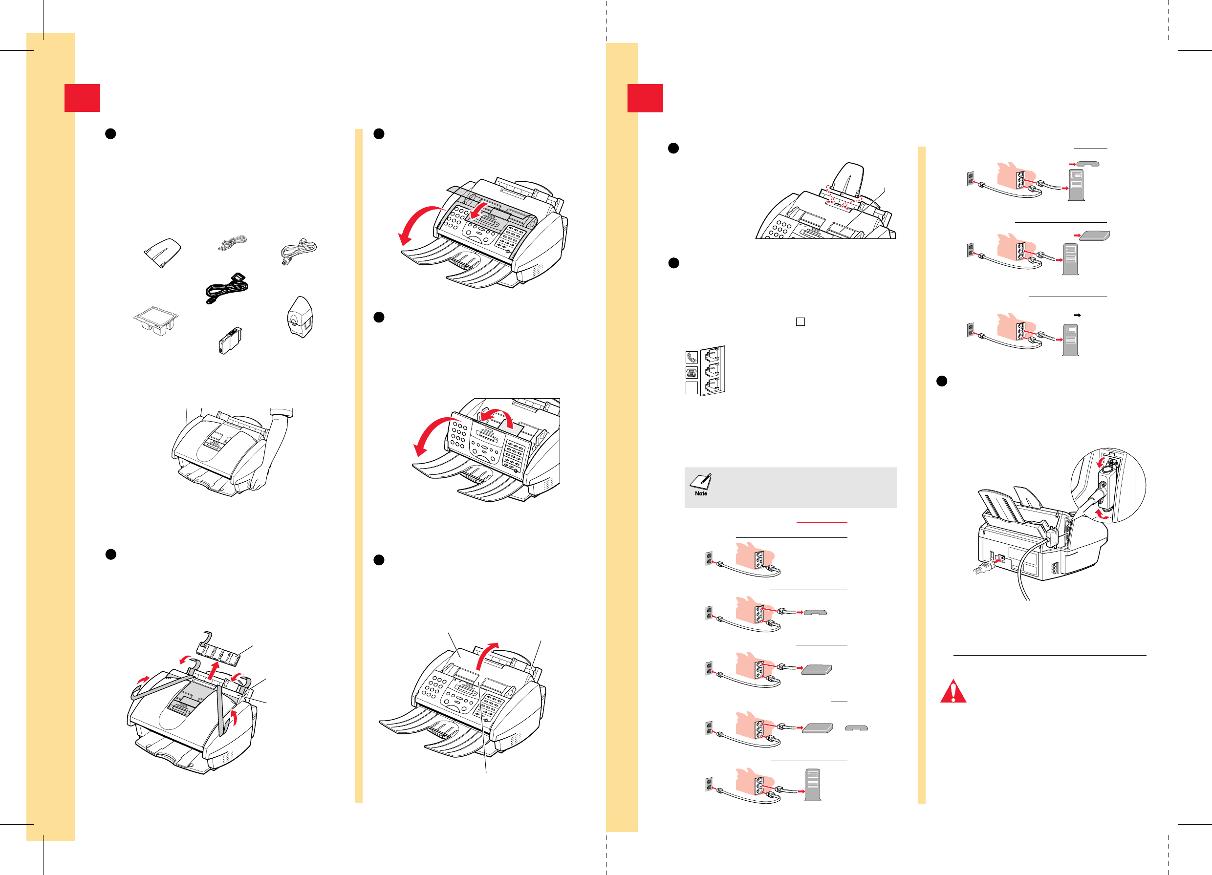
Set Up the MultiPASS
2
Attach the sending document support.
Fit the tabs on the sending
document support into the
slots above the ADF.
Make sure the
support curves
toward the back
of the unit.
1
Connect the phone line.
2
Connect the USB—to—Parallel cable
and power cord.
3
Make sure the computer is turned off.
Connect the USB—to—Parallel cable to the
MultiPASS and to your
computer.
Place the main unit of the MultiPASS on a level surface with plenty of room to work.
L
If you have only one telephone line and plan to use the
MultiPASS for receiving both faxes and voice calls, you
must attach a telephone and/or answering machine to
the unit.
Power Cord
(to outlet)
USB—to—Parallel Cable
(to computer)
Connect the power cord to the MultiPASS and to
a wall outlet. The MultiPASS has no power switch.
The power is on as long as the system is plugged in.
ADF
Jacks on
MultiPASS
The MultiPASS unit has three telephone jacks (located
on the left side of the unit) that will accept standard
line connections.
L
Use the bottom jack to connect the wall
jack to the MultiPASS with the supplied
line cord (unless connected with Caller ID).
The other two jacks are pass-through ports
to connect other devices to the MultiPASS
and your telephone service. Select from the
options in the diagram below to configure
your telephone device to work in
conjunction with your MultiPASS.
MultiPASS Only
Recommended Device Connections Receive Modes
Fax Only
or DRPD
Wall Jack
MultiPASS and Telephone Fax/Tel, DRPD,
or Manual
Wall Jack
MultiPASS and Answering Machine Ans.Machine
Wall Jack
Telephone
Answering
Machine
MultiPASS, Answering Machine and Telephone
Ans.Machine
Wall Jack
Answering
Machine
Telephone
MultiPASS and PC Modem Fax Only
or DRPD
Wall Jack
PC
MultiPASS, PC Modem and Telephone
Wall Jack
PC
Telephone
MultiPASS, PC Modem and
Answering Machine
Wall Jack
PC
Telephone
Answering
Machine
MultiPASS, PC Modem, Answering
Machine and Telephone
Wall Jack
PC
If you use Caller ID with any of these
configurations, place the Caller ID device
between the MultiPASS and the wall jack.


