


10 P114F Stackable Switch Installation Guide
Diagnostics
Table 1 and Table 2 explain the meaning of the P114F Stackable Switch diagnostic
LED indicators.
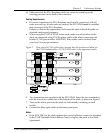
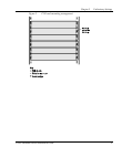
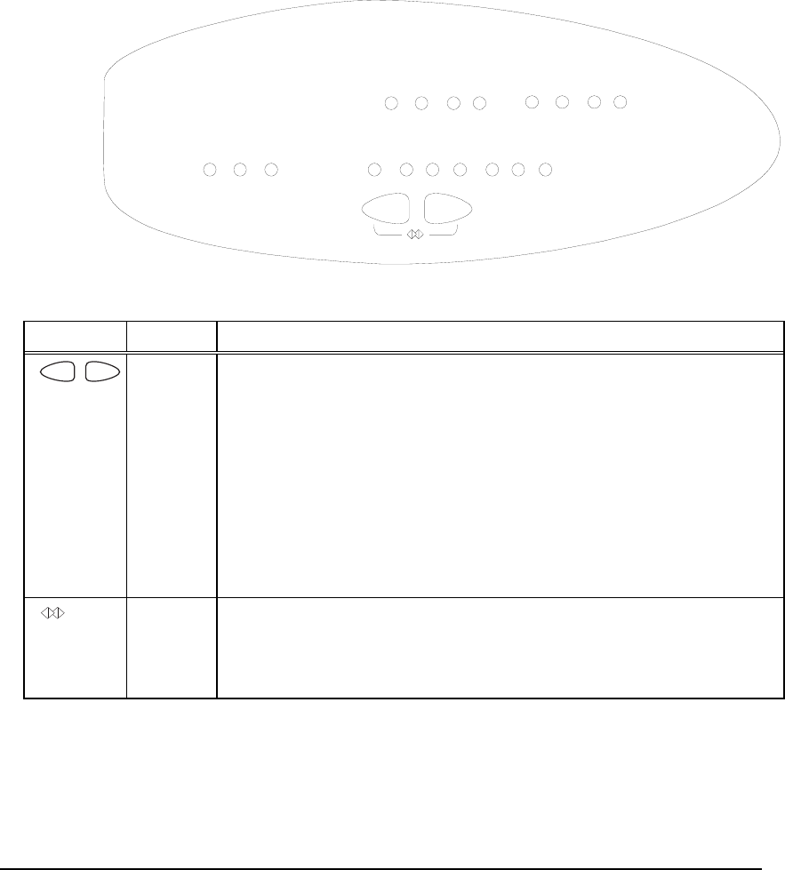
Figure 3 The P114F Stackable Switch Front Panel LEDs and Buttons
PWR NMA RED
NMA
LNK
COL 100 M
Tx FDX
FC
Rx
34 5 6 7812
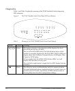
Table 1 Meaning of the P114F Stackable Switch Front Panel Buttons
Button Function Meaning
Select The buttons determine what function will be displayed by the 8
Port LEDs (the top row of LEDs).
The seven Function LEDs (above the Select buttons) show which
function is currently displayed by the Port LEDs. The Port LEDs can
display either Link, Collision, Transmit, Receive, Full Duplex, Flow
Control or 100 M status.
If, for example, the Link (LNK) LED is lit then LEDs 1 to 8 will
display the Link status of every port.
Press the left or right button to toggle the Port LED display between
functions.
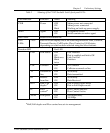
Reset Press Reset to return a malfunctioning switch to proper operation.
Press and hold both buttons simultaneously for a second or more to
reset the entire P110 stack. Upon Reset, all LED indicators turn on.
Pressing Reset does not affect configuration settings.