


Chapter 2 Preliminary Settings
P114F Stackable Switch Installation Guide 7
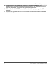
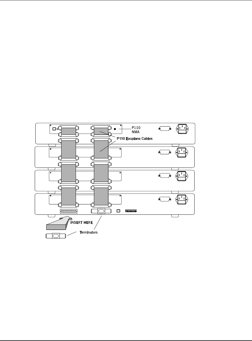
Make sure that the P110 Exoplane cables are correctly seated by gently
exerting pressure on the back of the connector.
Cabling Requirements:
• For correct operation, the P110 Exoplane must be fully connected, with all
units powered up. In case units are stacked, the P110 NMA must be installed
and connected to the P110 Exoplane.
Failure to observe this requirement will cause the units to block all traffic on
attached stations and segments.
• When using the P114T or P114F in the stack, make sure all switches in the
stack are connected using P110 Exoplane cables with white connectors and
marked C/S:B (part number 108362203). Extra cables can be ordered from
your local Avaya representative.
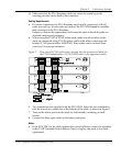
Figure 1 Rear view of a P110 switch stack, showing how the switches are linked via
the P110 Exoplane cables. A P110 NMA resides in the uppermost switch.
6. Two terminators are supplied with the P110 NMA. Insert the two terminators
into the lowest two connectors at the bottom of the stack, as shown in Figure 1.
7. Turn on the mains power to the stack, by individually switching on each
switch.
8. Connect the fiber-optic cables to the front panel ports.
Notes:
• If the P110 NMA in the stack contains the correct software version (as specified
in the P114F Stackable Switch Release Note) or higher, the stack is now fully
operational.