


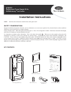
INSTALLING THE NEW POWER SUPPLY:
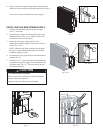
1: Strip the red and black replacement power supply
wires ¼” from ends.
2: Insert the high voltage wires through the holes in the
enhancement face (Fig. 10-A). Make sure the wires
do not kink or have twists in them.
3: Mount the new power supply module to the
enhancement module using the four screws removed
earlier (Fig. 10-B).
NOTE: Make sure the green ground wire runs down
the groove in the enhancement module face behind
the power supply enclosure.
4: Reconnect the green ground wire to the enhancement
module (Fig. 11).
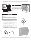
5: Crimp the new ¼” quick disconnect terminal onto the
red replacement power supply wire and connect to the
ionization array (Fig. 12). This may require the use
of needle-nose pliers.
Fig. 10-A
Fig. 11
Fig. 10-B
Fig. 12
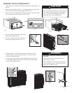
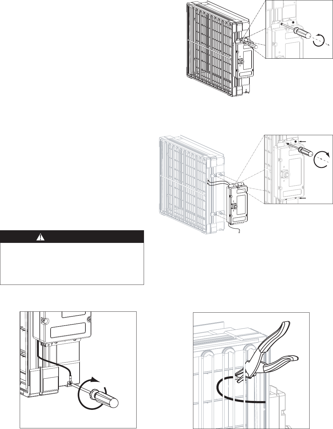
8: Remove the power supply module from the enhancement
module by unscrewing the four Phillips head screws (Fig. 9).
You are now ready to install the new power supply.
UNIT OPERATION HAZARD
Failure to follow this caution may result in equipment
damage or improper operation.
Improper wiring will reduce unit performance.
CAUTION
Fig. 9
2 Screws
2 Screws