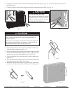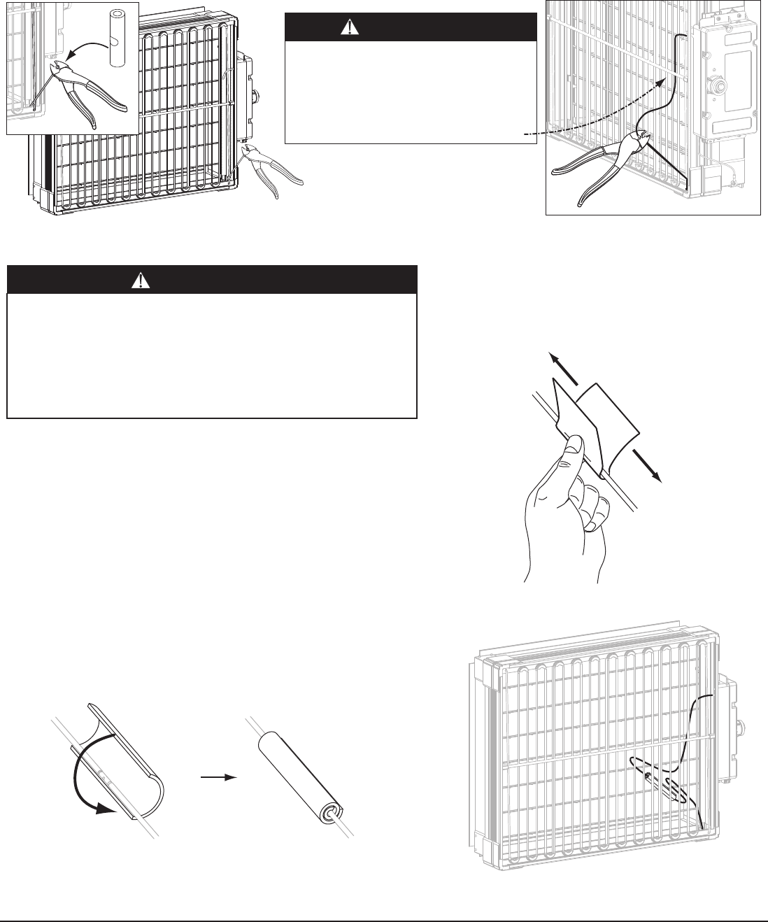
8: Clean the butt connector and at least two (2) inches of the wires on
either side with the alcohol swab (Fig. 15).
9: Remove the backing paper from the splice insulation tape and center
on the butt connector along the length of the tape. Tightly wrap the
insulation tape around the butt connector and wires (Fig. 16).
10: Tuck the completed splice behind the media cartridge enhancement
grid (Fig. 17).
11: Insert the enhancement module back into the air purifier cabinet and
reconnect the power and air flow sensor cables.
12: Replace the door, turn the Infinity
TM
air purifier power switch to the
on position, and turn on the power to the heating and cooling system.
Fig. 16 Fig. 17
Fig. 15
Fig. 13 Fig. 14
6: Crimp the butt connector to the severed media cartridge enhancement grid wire (Fig. 13). Please note that the grid wires will
typically be black.
7: Crimp the opposite side of the butt connector to the black replacement power supply wire (Fig. 14).
Copyright Carrier Corp. • 7310 W. Morris St. • Indianapolis, IN 46231 Printed in China Edition Date: 2/07 Catalog No. IIK63000-C01
Manufacturer reserves the right to discontinue, or change at any time, specifications or designs without notice and without incurring obligations. Replaces: New
UNIT OPERATION HAZARD
Failure to follow this caution may result in equipment damage or
improper operation.
At this point it is critical that your hands are clean before applying the
splice insulation tape around the butt connector. Dirt and/or oil can
contaminate the insulation and cause the splice to fail.
CAUTION
UNIT OPERATION HAZARD
Failure to follow this caution may result in
equipment damage or improper operation.
Make sure the high voltage wire is routed
behind the horizontal fiberglass rod.
CAUTION


