


CBM-710/720/730/750 User’s Manual
22 CITIZEN
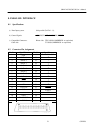
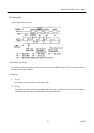
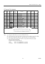
8.3 Description of Input/Output Signals
(1) Input/Output Signals
a) Input Signals (To Printer)
*DATA : 8 bit parallel signal. (Positive logic)
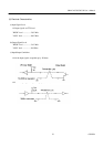
*STB : A strobe signal for reading in 8 bit data. (Negative logic)
*RESET : A signal which resets the entire printer. (Negative logic. 1 ms or more)
b) Output Signals (From Printer)
*ACK : This is a pulse signal for requesting 8 bit data, issued at the end of a BUSY signal.
(Negative logic)
*BUSY : This signal indicates that your printer is in a BUSY state. New data should be input
when this signal is "LOW". (Positive logic)
*FAULT : When your printer is in an alarm state, this signal is "LOW". At this time, all control
circuits of your printer are interrupted. (Negative logic)
*PE : When the paper is near its end, this signal is issued. (Positive logic)
Note: An alarm condition occurs when the timing of the print head movement sensor is abnormal.
c) Power Source
*+5V DC : The same +5V output as that of the power source which actuates the control circuits.
This should be less than 30 mA.
*GND : The common circuit ground.
*FRAME GND : Equivalent to "case ground".