


Step 5
Replace GCU cover and mount
near gate operator control box.
Step 6
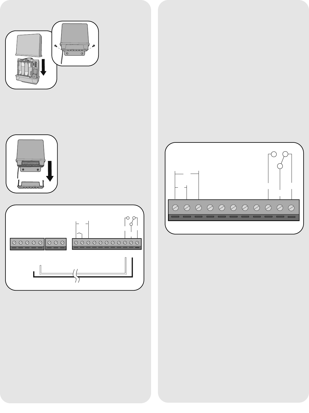
Remove bottom panel of GCU.
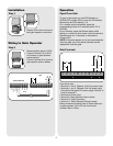
Connect Terminal 10 on GCU
to Common on gate operator
(shown below).
Connect Terminal 9 to Cycle on
gate operator (shown below).
132 4567891011
DC
AC
+
-
COM
N/C
EXIT
SAFETY
EDGE
COMMON
OPEN
GRN
BLK
RED
RECR
N/O
GATE OPERATOR
GCU
Installation
Wiring to Gate Operator
2
Operation
To open a gate enter any valid PIN Number on
GAPLM. For multiple GCU’s, enter the PINNumber
followed by the GCU Identity (1-4).
For a remote control transmitter, press the
corresponding button for 3 seconds (within 75' of
GAPLM).
On an Intercom, press the Remote button while
talking to a visitor. At other times, hold the intercom’s
Remote button for 10 seconds, to activate the
Primary GCU.
NOTE: If the gate operator is not set to automatically
close the gate, any of the above methods can be
repeated to close the gate.
Open/Close Gate
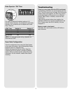
132 4567891011
DC
+
-
N/O
COM
N/C
AC
Gate Terminals
From left to right:
• Terminals 1 and 2: Optional 10-24 Vac power input.
• Terminals 1 and 3: Optional 9-24 Vdc power input.
Ensure that the gate’s DC power supply “Ground” is
wired to terminal 3.
• Terminals 4-8: Not used.
• Terminal 9: Relay Normally Open contact.
• Terminal 10: Relay Common.
• Terminal 11: Relay Normally Closed contact.
Relay connections typically wire to Open Gate input
on gate operator. Up to 120 Vac Low current
contacts. Max 1/2 Amp.