


Operating Instructions
ART-575W User Manual 13 2006-06-15/17:08
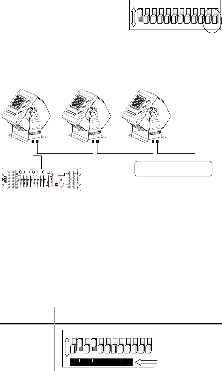
ON
1
2
3
4
5
6
7
8
9
10
11
12
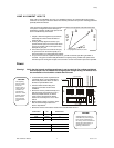
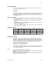
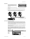
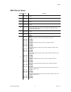
DMX Mode: Set Dipswitches 11 & 12 to Off
120ohm
The ART-575W utilizes 8 control
channels in DMX mode.
ON
1
2
3
4
5
6
7
8
9
10
11
12
1
2
4
8
16
32
64
128
256
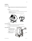
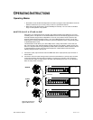
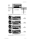
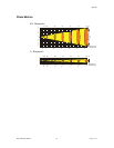
Binary values
DMX MODE
Operating in a DMX Control mode environment gives
the user the greatest flexibility when it comes to
customizing or creating an environment. Simply
address all fixtures sequentially and use any universal
DMX controller.
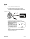
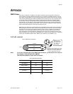
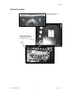
1) Create the serial data link by connecting all fixtures in
a daisy chain.
2) Connect the (male) 3 pin connector side of the DMX cable to the output (female) 3 pin connector of
the first fixture.
3) Connect the end of the cable coming from the first fixture which will have a (female) 3 pin connector
to the input connector of the next fixture consisting of a (male) 3 pin connector. Then, proceed to
connect from the output as stated above to the input of the following fixture and so on.
SETTING THE STARTING ADDRESS
This DMX mode enables the use of a universal DMX controller device. Each fixture requires a "start
address" from 1 to 511. A fixture requiring one or more channels for control begins to read the data
on the channel indicated by the start address. For example, a fixture that occupies or uses 6 channels
of DMX and was addressed to start on DMX channel 100, would read data from channels: 100, 101,
102, 103, 104, and 105. Choose start addresses so that the channels used do not overlap and notate
the start address selected for future reference.
If this is your first time addressing a fixture using the DMX-512 control protocol then I suggest jumping
to the Appendix Section and read the heading “DMX Primer”. It contains very useful information that
will help you understand its use.
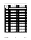
Set the start address using the group of dipswitches located underneath the top cover of the fixture
illustrated in the Appendix Section “Dipswitch Location”. Each dipswitch has an associated value.
Adding the value of each switch in the ON position will provide the start address. Determining which
switches to toggle ON given a specific start address can be accomplished in the following manner. By
subtracting the largest switch value possible from the selected start address which does not cause a
negative number.
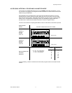
EXAMPLE DMX CHANNEL
ADDRESS THE DMX CHANNEL ADDRESSES WERE SELECTED AT RANDOM.
CHANNEL 10
PIN # 4= 8
PIN # 2= 2
TOTAL = 10