


CMA351 Installation Instructions
6
Installation
IMPORTANT ! : These installation instructions assume
that a 1-1/2" NPT or NPSM following ANSI/ASME B1.20.1
(Schedule 40, 0.154" minimum thickness aluminum-ASTM
B221) threaded extension column (not included) has been
properly installed and is in place.
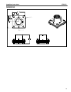
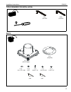
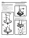
1. Place one Nylon washer (C) over each stud on swivel
adapter (A). (See Figure 1)
2. Align slots in stop plate (B) with two threaded studs on
swivel adapter (A). (See Figure 1)
3. Secure stop plate (B) to swivel adapter (A) using two lock
nuts (D). (See Figure 1)
NOTE: DO NOT fully tighten lock nuts at this time.
Figure 1
4. Thread swivel adapter (A) onto existing 1-1/2" NPT or
NPSM threaded extension column until tight, with a
minimum of four threads engaged. (See Figure 2)
5. Secure swivel adapter (A) to extension column using 5/16-
18 x 3/8" set screw (F) and hex wrench. (See Figure 2)
Figure 2
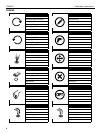
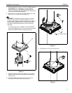
6. Rotate the bottom of swivel adapter (A) until middle set
screw in swivel adapter (A) makes contact with tab in stop
plate (B). (See Figure 3)
NOTE: This is considered the first stop position.
Figure 3
1
2
3
(C) x 2
(D) x 2
(A)
(A)
(B)
4
5
(F)
(A)
6
TOP VIEW
Tab
Lower Set
Screw
Lower Set
Screw
Tab
(Not Visible)
(B)
(A)