


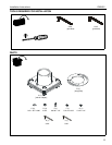

Installation Instructions CMA351
7
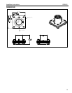
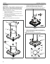
7. Using a pipe wrench, install 1-1/2" NPT or NPSM following
ANSI/ASME B1.20.1 (Schedule 40, 0.154" minimum
thickness aluminum - ASTM B221) threaded extension
column (not included) into swivel adapter (A) until tight, with
a minimum of four threads engaged.
8. Secure lower 1 1/2" NPT pipe to swivel adapter (A) using
#10-24 x 1/4" set screw (G). (See Figure 4)
WARNING: Exceeding the weight capacity can result in
serious personal injury or damage to equipment! It is the
installer’s responsibility to make sure the combined weight of
all components located between the CMA351 up to (and
including) the display/projector does not exceed 500 lbs
(226.8 kg).
The weight capacity of the CMA351 may be LIMITED to
the lowest weight capacity of any other component located
between the CMA351 and the supporting structure!
Figure 4
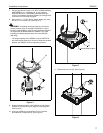
9. Rotate the bottom portion of the CMA-351 to the desired
location for the second stop (0 degrees to 330 degrees).
(See Figure 5)
10. Insert one Phillips pan head screw (E) in the nearest
threaded hole in stop plate (B). (See Figure 5)
Figure 5
11. Tighten two lock nuts (D). (See Figure 6)
Figure 6
7
(G)
(A)
8
(B)
Second Stop Location
(E)
(D) x 2