


Page 2 of 3
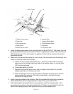
1. Thread Locking Screw 6. Adapter Plate
2. Power Inlet 7. Hanging Bracket Bolts
3. (4x) Locking Hasp 8. Pitch Adjustment Bolts
4. Power Switch 9. Adjustment
5. Rocker/Control Switch 10. Adjustment Nuts
4. Using the appropriate power cord, provide power to the EVCM-100. The power inlet is a
general-purpose IEC-320 power inlet for Class 1 applications rated at 10A international,
15A North America. The main plug to the appliance inlet shall be used as the primary
disconnect device.
5. Make sure the area directly below the unit is clear of all individuals and obstructions and
lower it to floor/service level as follows:
A Unlock the four locking clasps [See Fig. 1, Item (3)] on each side of housing,
making sure the locking clasps are clear of the keeper plates, by turning them
180°counter-clockwise.
B Turn power switch (4) to ON.
C Depress and hold the down arrow side of rocker/control switch (5) until the
adapter plate (6) is to floor/service level.
D With unit resting on floor or service platform, depress the down arrow side for
approximately four seconds. This will provide slack in the cable for easy
movement of adapter plate.
6. Attach hanging bracket to the projector. See the enclosed HB instructions (projector
Model determines which hanging bracket is required for your EVCM-100).
7. After attaching the hanging bracket to the projector, install the adapter plate to the
hanging bracket using six hanging bracket bolts (7) (three on each side) through the
holes in the hanging bracket and tighten securely into the adapter plate.
Figure 1
10
9
8
3
7
6
5
4
2
1
1 ½” NPT Cou
p
le
r